8.10.1 Overview
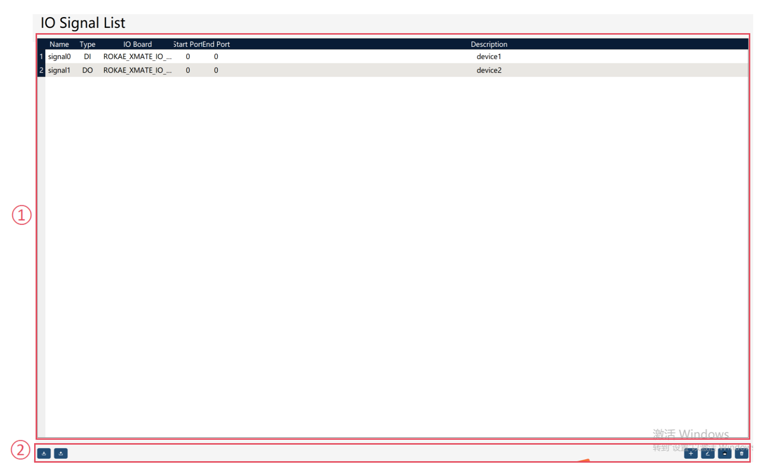
In addition to the default Universal IO signals created by the "IO device" in the enabled state, if you want to use the IO device alone to create a user IO signal, you need to create it on the "IO Signal List" page.
The signalxx type variables are used to store and access IO signals in the RL program. For details, refer to relevant sections about RL commands.
① |
IO signal list, where you can view IO signal attributes, including: * Signal name; |
② |
Function button area, where you can import, export, create, edit, multi-select, and delete IO signals |
|
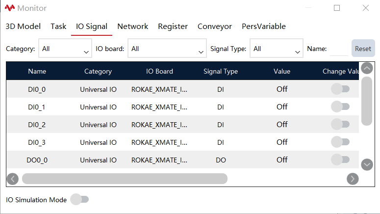
The configured IO can be viewed on the status monitoring interface, on which the forced output or simulation input of the IO is supported.
8.10.2 Operation examples
Operation |
Graphical Representation |
Explanation |
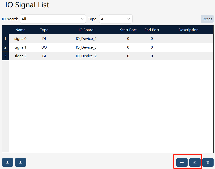
1. Click the "+" button in the lower right corner to create a new IO. |
|
Users with the permission level of "Programmer" or above can perform creation and edit operations. |
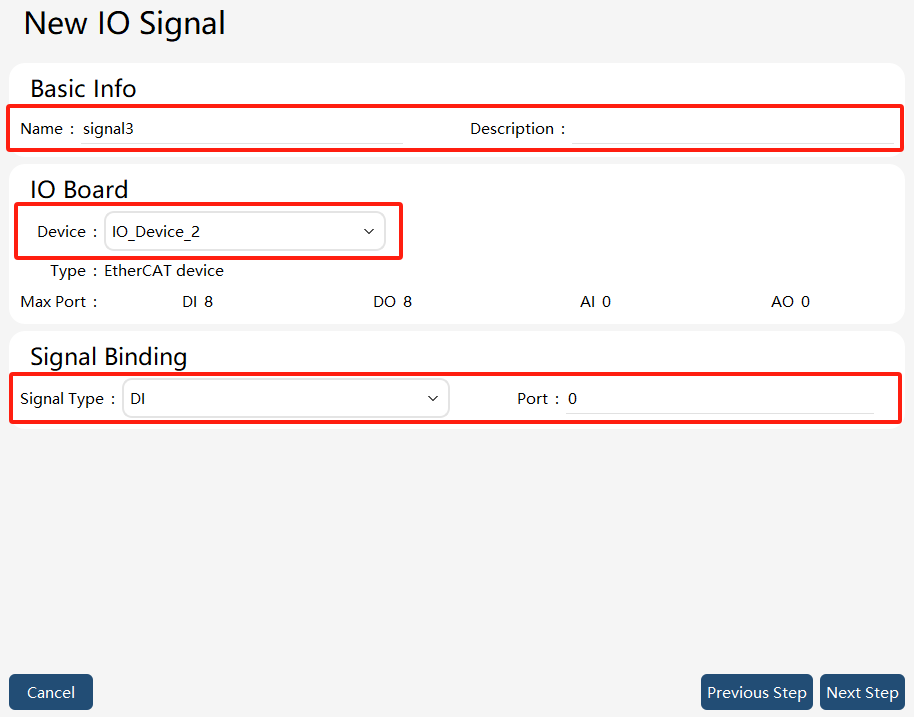
2. Attribute settings. |
|
Set IO signal name, description, IO board, signal type, and port. |
3. Using IO Signal in the RL program. |
|
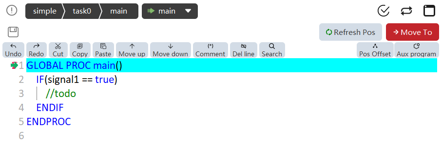
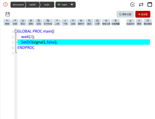
For the input signal (DI/GI), the state of the input node can be read directly in the RL program using the variable name of the input signal. For example: Use the state of the digital input as a criterion for judgment IF (di1 == true) do something… ENDIF For the output signal (DO/GO), specialized commands SetDO and SetGO can be used in the RL program. See the Explanation of each command below for details. |
8.10.3 IO signal export/import
8.10.3.1 IO signal export
On the IO signal list page, click the button at the bottom left to enter the IO signal export interface.
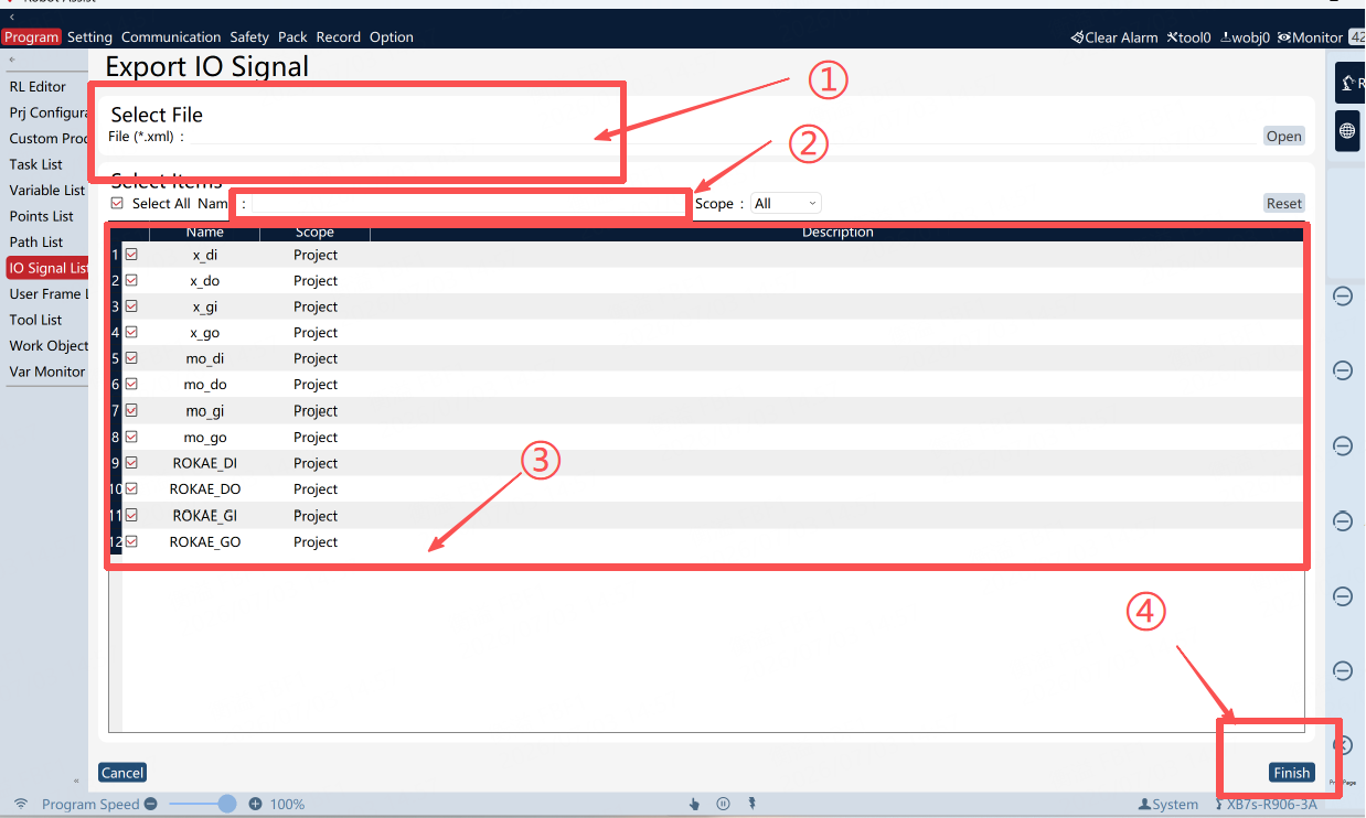
① |
IO signal export target file (including path) |
② |
Filter box |
③ |
IO signal list |
④ |
IO signal export button |
Export steps: First, input or select the path for the IO signal export target file in ①, and filter by name in ②, if necessary. Then, check the IO signals to be exported in ③. Finally, click the button in ④ to execute the export, and the exported IO signal file will be generated in the path specified in ①.
8.10.3.2 IO signal import
On the IO signal list page, click theimage::en/image271.png[width=700,align=center] button at the bottom left to enter the IO signal import interface.
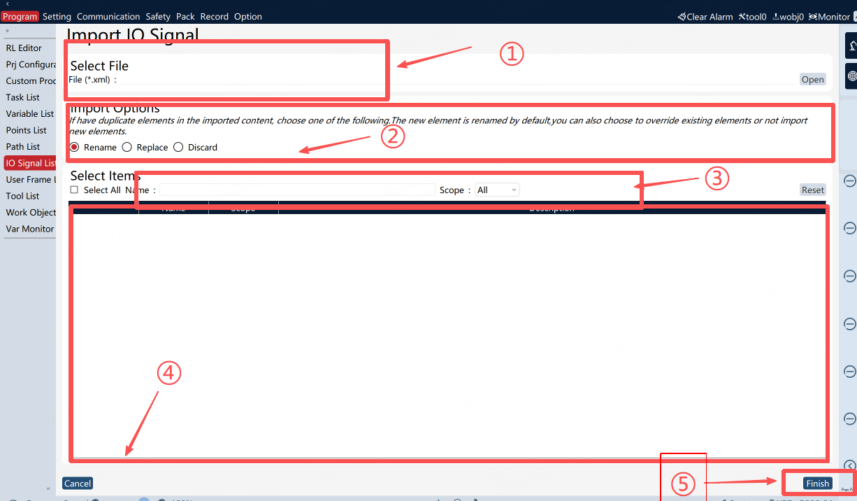
① |
IO signal import file |
② |
IO signal import option, which is the strategy for handling entry conflict |
③ |
Filter box |
④ |
IO signal import entry |
⑤ |
IO signal import button |
Import steps: First, select the IO signal file to be imported in ①, and filter by name in ③, if necessary. Then, select the conflict handling strategy in ② and the IO signals to be imported in ④. Finally, click the "Finish" button in ⑤ to execute the import, and the selected IO signals will be imported locally.