7.1 Introduction to this chapter
This chapter provides an overview of the most commonly used basic and requisite operations for robots.
Users need to read this chapter before actually using the robot.
7.2 Operating mode
Robot operating mode includes manual mode and automatic mode.
7.2.1 Switch manual
The manual mode is mainly used for robot programming and debugging. In manual mode, all robot motions are controlled manually by the user, and the robot will power on the motor and respond to the motion commands only when its motion is enabled (the three-position switch is in the middle position).
The manual mode is typically used to execute the following tasks:
-
Jog the robot back close to the path after an emergency stop to continue running the program;
-
Create and write RL programs;
-
Debug the RL program, including but not limited to start, stop, single-step run, and program position update;
-
Set control system parameters and calibrate frames;
-
View and modify variables;
7.2.2 Switch auto
The automatic mode is used for continuous automated production, in which the three-position enabling switch will be bypassed and the robot can work normally without manual intervention. When the robot is in automatic mode, the system IO signals, etc. can be used to control the robot and obtain the robot’s operating status.
The automatic mode is typically used to execute the following tasks:
-
Load, start, and stop the RL program;
-
Return to the original programming path after an emergency stop;
-
Back up the system;
-
Clean the tools (as per the process requirements);
-
Machine and process the work objects;
The usage restrictions in automatic mode include but are not limited to:
-
Not allowed to Jog.
-
Not allowed to modify configuration files, configure the number of IO boards, or set the robot installation method.
-
Not allowed to restore the backup.
-
Not allowed to grant function authorization.
-
Not allowed to set soft limits.
-
Not allowed to create, modify, and delete IO.
-
Not allowed to perform parameter identification.
-
Not allowed to turn on/off collision detection.
-
Not allowed to turn on/off collaboration mode.
-
Not allowed to turn on/off drag teaching in automatic mode.
-
Not allowed to perform calibration.
-
Not allowed to create new variables.
-
Not allowed to update or restore to factory settings.
7.2.3 Mode confirmation and switching
You can learn about the current mode of the control system by checking the mode icon on the bottom status bar of the HMI software.
|
The controller is in manual mode. |
|
The controller is in automatic mode. |


Users can switch between different operating modes by clicking the mode icon in the HMI interface. Before switching, a dialog box will pop up for confirmation, and if you click "OK", the system will switch the operating mode; and if you click "Cancel", the switching will be canceled.

Attention: For safety, when switching modes, the system will cut off the power supply. If the system is executing the RL program and the robot is in motion, the system will trigger STOP 1 to stop.
7.2.3.1 Switching from manual mode to automatic mode
When operators need to verify the programs at all states and speeds, or when the programs are ready for full production, the system can be switched to automatic mode.
You can switch from manual mode to automatic mode in the following ways.
Way I |
HMI button: Click the operating mode icon |
Way II |
System IO: "automatic mode". |
Way III |
External communication: "switch_mode:auto"+"\r". |
Way IV |
Register function code: ctrl_switch_operation_auto_manual. |
Way V |
SDK. |
In automatic mode, the robot may be triggered to move by an external signal without any warning. Before switching to automatic mode, it is necessary to make sure that collision detection is enabled to prevent personal injury from accidental collisions between the robot and personnel! |

7.2.3.2 Switching from automatic mode to manual mode
You can switch from automatic mode to manual mode in the following ways.
Way I |
HMI button: Click the operating mode icon |
Way II |
System IO: "manual mode". |
Way III |
External communication: "switch_mode:manual"+"\r". |
Way IV |
Register function code: ctrl_switch_operation_auto_manual. |
Way V |
SDK. |
7.3 Power on and off
Please first read the introduction to enabling devices in Safety devices, Chapter 2.
7.3.1 Motor on
In manual mode, the user can power on the motor by pressing the yellow three-position enabling switch on the handheld enabling device and holding it in the middle position. You can judge whether the power-on is successful by listening to the power-on sound of the robot or observing that the power-on button on the bottom status bar on the HMI software interface turns red.

|
If the power-on fails, observe the real-time log to determine the robot’s status at this time and switch the robot to a status available for power-on before trying again. |
In automatic mode, click the power-on button on the bottom status bar on the HMI software to power on the motor. The method to determine whether the motor is properly powered on in this mode is the same as that in manual mode.

7.3.2 Motor off
In manual mode, the user can power off the motor by releasing or pressing the yellow three-position enabling switch all the way down to keep it in Position 1 or Position 3.
In automatic mode, click the power-off button on the bottom status bar of the Robot Assist interface to power off the motor.
|
In case of emergency, press the emergency stop button on the manual enabling device for emergency robot power-off. When the robot needs to be powered on again, please reset the emergency stop switch manually. |
7.4 Motion control
7.4.1 Jog
Jog supports multiple frames/modes, as shown in the table below.
| Explanation | Remarks | |
|---|---|---|
World frame |
Cartesian space Jog, moving in the direction of a given frame. For example, if you select "world frame", Jog X, the robot will move in the X direction of the world frame; and if you select "tool frame", Jog B, the robot will rotate in the Y direction of the tool frame. |
|
Flange frame |
||
Base frame |
||
Tool frame |
||
Work object frame |
||
Singularity avoidance |
It is mainly used to avoid wrist singularities during Cartesian Jog, and all its XYZ motions are relative to the base frame. |
You need to first turn on the "Stacking Debugging Mode" on the "Advanced Settings" page under "Motion Parameters" of "Settings". The current version is applicable to robot models: industrial standard six-axis series (XB, NB models) and xMate CR/SR collaborative series. |
Parallel base |
It is mainly used to avoid wrist singularities during Cartesian Jog, and all its XYZ motions are relative to the base frame. |
|
Joint space |
Each axis movement is controlled individually. |
|
Due to the configuration limitation of the xMate series 5-axis robots, when Jog xyz is performed in the ordinary frame, the robot’s orientation will change along with the arm plane rotation. During Jog A, the robot flange will rotate around the normal of the arm plane. Jog B is the same as Jog Axis 5 in joint space. The C button is invalid. |
Jog supports two modes: continuous and stepping:
-
In continuous Jog mode, when the robot is powered on and the jog button is held down, the robot will move continuously at the set Jog velocity until either the enabling switch or the Jog button is released.
-
In stepping Jog mode, after the robot is powered on, every time the Jog button is pressed, the robot moves for a given step length. Users can choose the appropriate step length according to their needs, which is mainly for accurately adjusting the pose of the robot.
|
In stepping Jog mode, it is necessary to hold down the Jog button and wait until the robot moves for the specified step length before releasing the Jog button. A short press can make the robot stop moving in advance. |
Jog speed setting:
Jog speed can be set to control the robot motion speed during Jog, with the speed range from 0.1% to 100% (100% corresponds to the robot’s top TCP speed of 250 mm/s). Subject to safety regulations, the TCP linear speed in both Cartesian space Jog and joint space Jog shall not exceed 250mm/s.
7.4.1.1 Jog low-speed mode
To facilitate users' fine adjustment of motion points, in the Continuous Jog mode, if the Jog speed is configured to 1% or below, the robot will enter Jog low-speed mode.
In this mode, the robot’s motion speed will be locked at 20%, while the step length for single Jog clicks will follow the table below.
| Jog Speed | Joint Space JOG | Cartesian JOG |
|---|---|---|
1% |
1.0° |
1.0 mm |
0.5% |
0.5° |
0.5 mm |
0.1% |
0.1° |
0.1 mm |
7.4.2 Quick adjustment
The right operation interface of the HMI provides a quick pose adjustment function. The supported quick pose adjustments include: Initial Pose, Drag Pose, Shipping Pose, and Home Pose.
The quick pose adjustment is available in manual mode in a way similar to Jog operation. In manual mode, the robot is powered on via the enabling switch. When the button for the corresponding target pose is pressed, the robot will move to the target pose in the joint space. The motion speed can be adjusted via the Jog speed.
Drag Pose, Shipping Pose, and Home Pose support user customization, which can be set on the "Quick Adjustment" page under the "Settings". If their parameters are not set, their default configuration is used.
7.4.3 Drag
During point teaching, the programming time can be greatly shortened by dragging and positioning; Robot dragging, combined with trajectory recording and trajectory reproduction, can simplify the difficulty of teaching in some continuous trajectory scenes.
Please refer to the Appendix for the introduction and usage examples of the end-effector handles of each collaborative robot model.
Attention: The Drag Mode and its extended functions (end-effector handle, point teaching, continuous trajectory teaching, and trajectory reproduction) are only available for xMate series cobots.
| Drag mode | Type | Explanation |
|---|---|---|
Joint space |
Each axis moves independently and can be directly adjusted to reach the desired pose; |
|
Cartesian space |
Translational drag only |
The robot can be guided to translate along all directions of Cartesian space; |
Rotational drag only |
The robot can be directly guided manually to rotate around TCP; |
|
Free drag |
Translation and rotation are supported in Cartesian space; |
When the robot is in manual mode and powered off, turn on the drag enabling switch on the operation interface, the robot is powered on automatically and enables Drag Mode. Press the enabling button on the end-effector drag handle simultaneously to drag the robot for point teaching and trajectory recording.
|
The appropriate drag way and drag space are set before the Drag Mode is enabled. After Drag Mode is enabled, the robot will be powered on automatically. In this case, the drag mode and drag space cannot be set, and you need to turn off Drag Mode before setting them. |
|
Before enabling Drag Mode, please make sure the robot’s dynamic parameters and load parameters are set accurately. Otherwise, enabling Drag Mode may fail, or the robot may float during dragging. Set the parameters using the dynamic parameter identification function and the load identification function provided by the system. |
The following parameters must be set correctly before the drag teaching is used,otherwise, when the angle of each axis is in the wrong state, the controller cannot calculate the correct output torque, and the robot drag function cannot be used normally.
|
7.5 Continuous trajectory playback
After a successful continuous trajectory teaching, playback the recorded trajectory on the recording interface and confirm, and then save it manually after confirmation.
Check Loop in the playback mode for looped playback.
The playback rate can be set between 1% and 300%. It is recommended that users set the playback rate in the range of 1% to 100%. When the playback rate is greater than 100%, a following error of the drive may occur.
For operation examples, refer to the section below, "Programming"-"Path list".
7.6 Operation example I: Industrial robots realize Jog motion
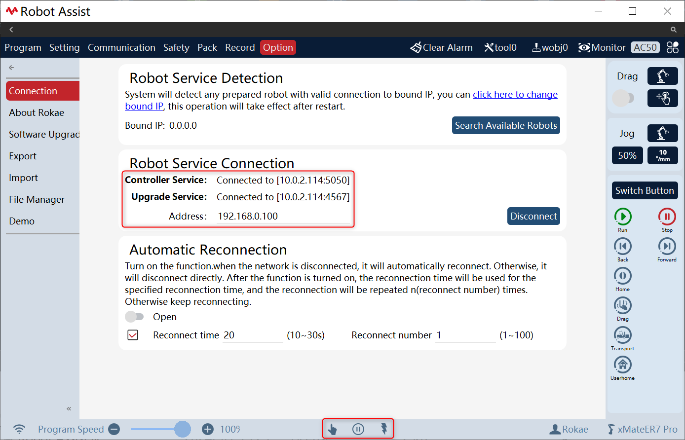
Before the real robot operation, it is necessary to ensure that the HMI is connected to the robot and both are powered on and operating normally. (see Chapter 5 for details).
| Step | Graphical Representation | Explanation |
|---|---|---|
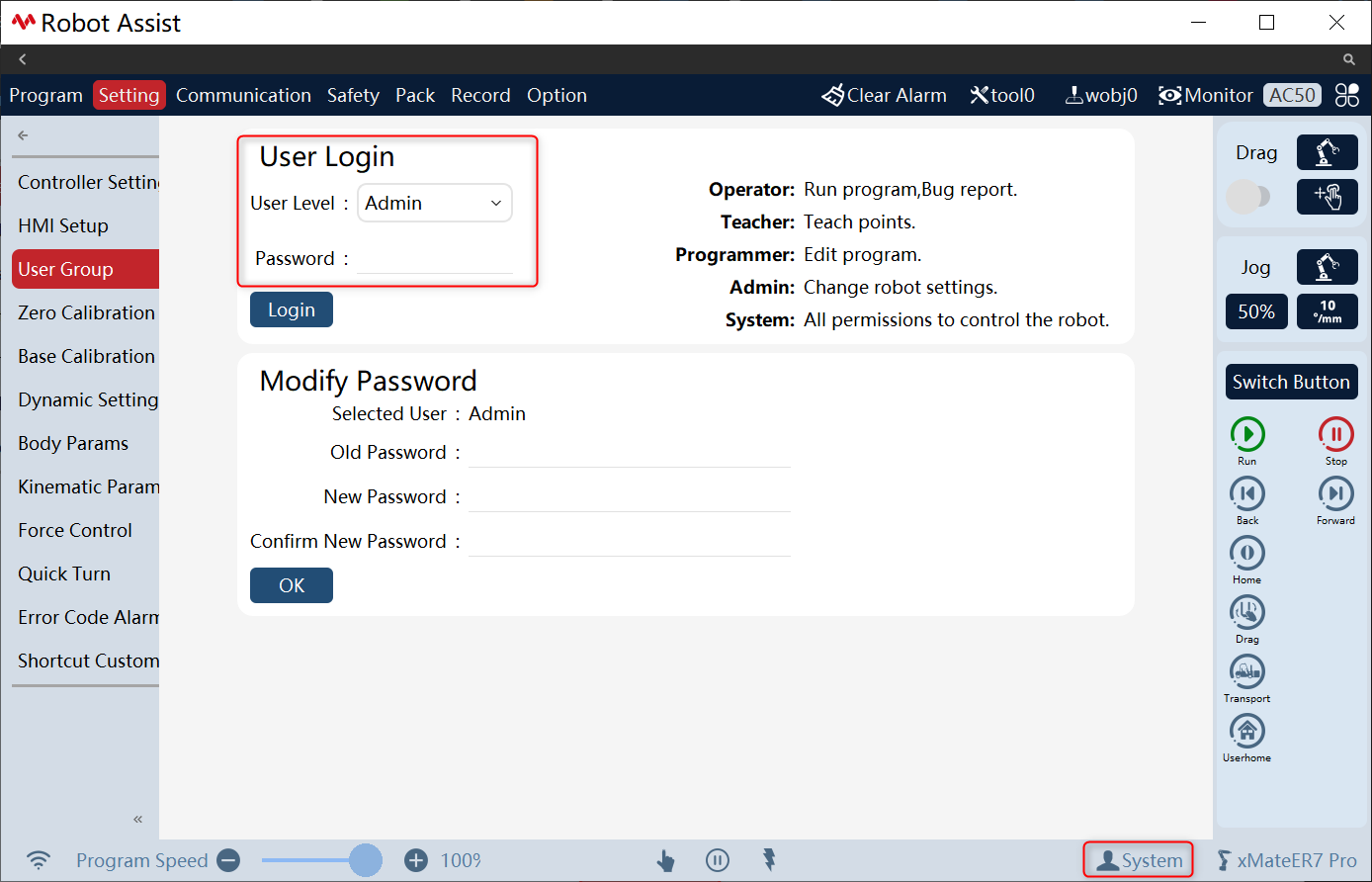
1. Check robot status. Ensure that the robot is normally connected and is in manual mode; |
|
|
2. Switch login user. |
|
|
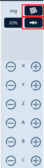
3. Select [Base Frame] as the Motion Frame. The specific frames are detailed in Chapter 4. Also, choose [Continuous Motion]. |
|
The movement direction of the manipulator end-effector is the same as the direction of the base frame. |
4. Hold the enabling switch of the Teach Pendant. |
|
When the manual power-on is successful, there will be an obvious power-on sound, and the robot status bar will show that the robot is in the manual power-on state. During jog, it is necessary to keep the enable switch pressed. |
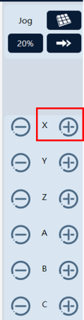
5. Jog the robot. Click on the teach pendant to select the desired direction for movement. This example demonstrates moving in the positive X-direction of the base frame. |
|
In continuous jog mode, it is necessary to ensure that the motion button remains pressed. Once the motion button is released, the robot will stop moving. |
6. Turn off Jog. Release the robot motion button, and release the enabling button. |
|
After the manual power-off, the robot status bar will show that the robot is in the manual power-off state. |


7.7 Operation example II: CR collaborative robots realize drag
Before the real robot operation, it is necessary to ensure that the HMI is connected to the robot and both are powered on and operating normally. (see Chapter 5 for details).
This section demonstrates the drag function of collaborative robots mainly based on the xMate CR7 collaborative robot.
| Step | Graphical Representation | Explanation |
|---|---|---|
1. Check robot status. Ensure that the robot is normally connected and is in manual mode; |
|
Make the robot in Drag Pose as much as possible. Make sure that the drag button is set to the non-selectable state when the robot is in automatic mode. |
2. Switch login user. |
|
|
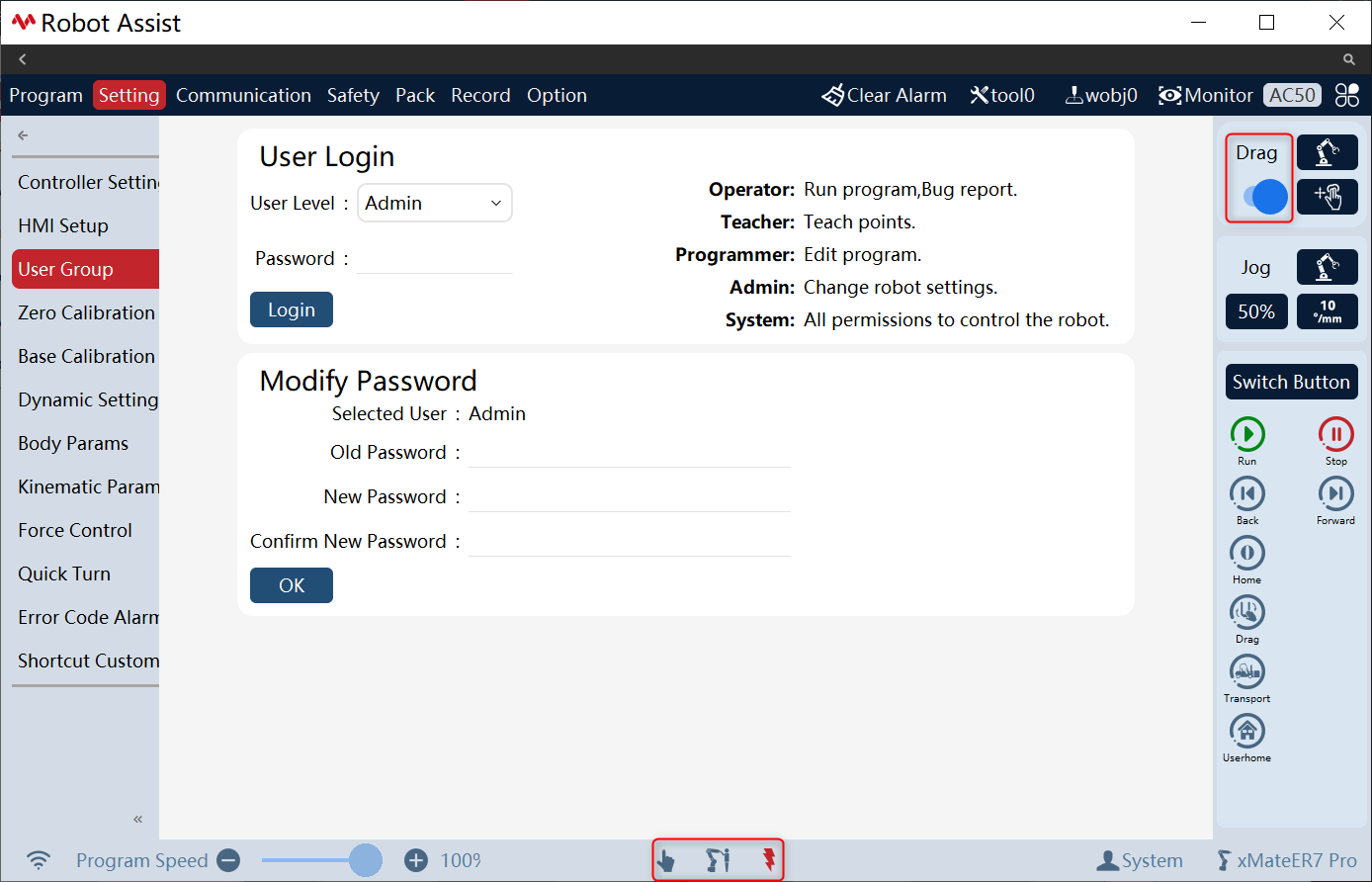
3. Click [Drag] button. The drag button will show that the drag button is activated, the robot status bar will show that the robot is in Drag mode, and the robot will make an obvious power-on sound; |
|
|
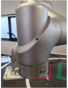
4. Press and hold the drag enabling switch of the robot to drag the robot to any position in the robot’s workspace; |
|
During drag, hold down the drag button to perform drag operation. |
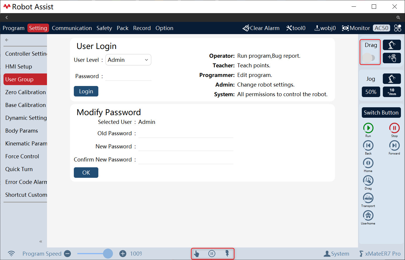
5. Release the robot drag enabling switch and click the [Drag] button. The drag button will show that the drag button is turned off, the robot status bar will show that the robot is in manual power-off mode, and the robot will make an obvious power-off sound. |
|
Other operations are allowed only after the drag state is exited. |