6.1 Introduction to this chapter
This chapter outlines the basic layout of xCore’s HMI software and the distribution and role of its main functions.
Users need to read this chapter before actually using the robot.
6.2 RobotAssist introduction
RobotAssist is the host computer software of the xCore control system, with functions including robot motion control, task editing, parameter setting, and status monitoring. The software can be installed on PC, Surface, and xPad2 Teach Pendant. The devices can control a robot after being connected to it as long as they are in the same network segment as the robot.
When you use the xPad 2, if the teach pendant encounters a crash or blue screen issue, the RobotAssist software will automatically restart to resume operation. (Please note that this auto-restart feature is not applicable to the PC side.)
Besides xPad2, we suggest using a tablet or a laptop as the operating terminal. The recommended configurations are shown in the table below.
Terminal type |
Tablet |
Terminal type |
Laptop |
ROM |
32 GB |
ROM |
32 GB |
RAM |
4 GB |
RAM |
4 GB |
Screen size |
8.0 inches and above |
GPU |
Intel HD Graphics 4000 or higher |
Network communication |
Wi-Fi |
Network communication |
Wi-Fi or wired LAN |
Operating system |
Windows 7 64 bit, Windows 10 64 bit, Ubuntu20.04 |
||
CPU |
Intel Core I3 and above |
||
|
Robot Assist interacts with the controller in real time. When it is used on a PC, frequent changes in window size may cause the interface to stop refreshing. In this case, you can restore it by pressing Alt+Tab to switch between windows. |
6.3 Interface for boot language settings
The interface for boot language settings is available to select the language pack. During the first boot, you can choose the language as needed.
After performing system cleaning, restoring factory settings, or clearing configurations, you can re-enter the interface for boot language settings.
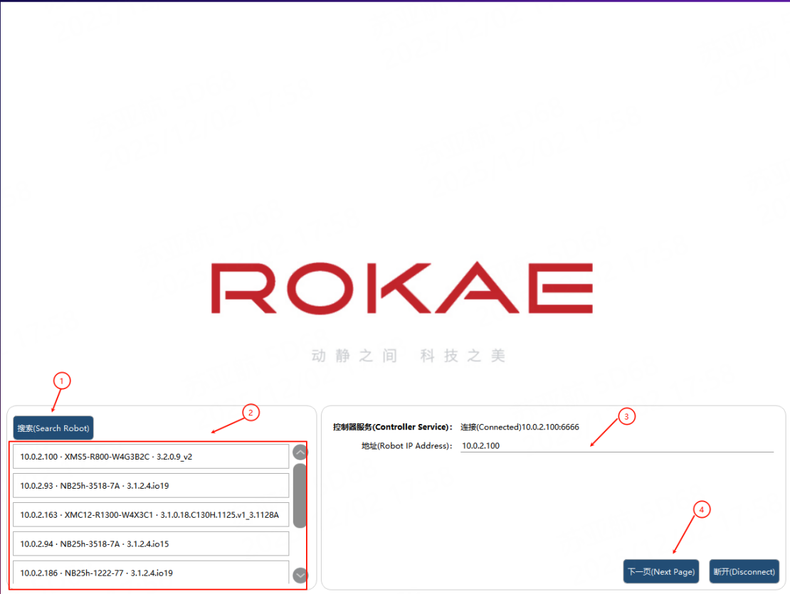
① |
Search button |
② |
All the robots searched within the local area network |
③ |
Robot IP, automatically obtained or manually input |
④ |
Click the "Next" to enter the interface for language settings |
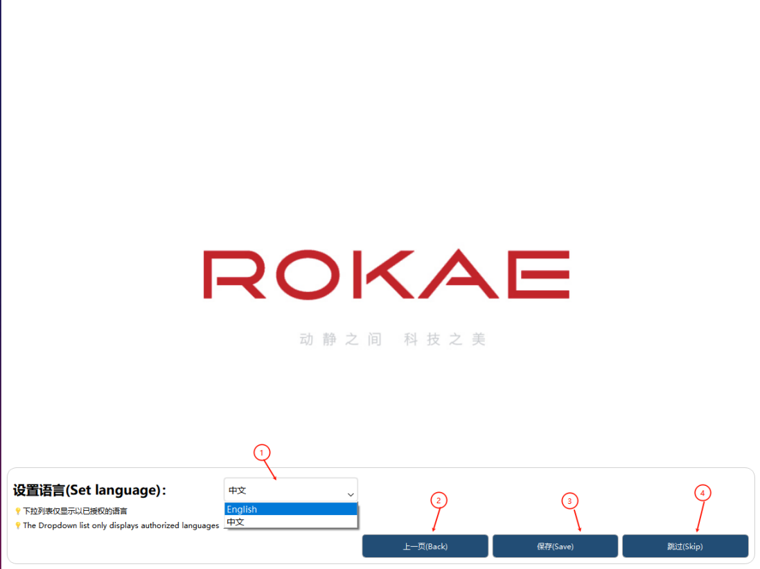
① |
Display all authorized languages |
② |
Click the "Back" to return and reconnect the robot |
③ |
Click the "Save" to switch to the currently selected language |
④ |
Click the "Skip" to maintain the current settings |
6.4 General layout of HMI
The main operation interface is usually composed of 4 main areas, including: top status bar, bottom status bar, left sidebar, and right operation interface.
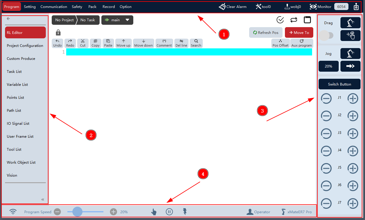
① |
Top status bar |
② |
Left sidebar |
③ |
Right operation interface |
④ |
Bottom status bar |
6.4.1 Top status bar
Top status bar, including: several first-level menu buttons (programming, settings, communication, safety, process package, log, options), instant log, clear alarm button, tool information button, work object information button, status monitoring button, RSC reset button, security check button, and operation interface button.

① |
First-level menu buttons, including programming, settings, communication, safety, process package, log, and options. Click one of the above buttons to go to the corresponding sub-interface; |
② |
Instant log, showing the latest controller log information of the system. Click it to go to the controller log sub-interface; |
③ |
Clear alarm button. Click it to clear the alarm status of the instant log and the controller; |
④ |
Tool selection button, displaying the information of the tool used currently. Click it to select the tool to be used; |
⑤ |
Work object button, displaying the information of the work object used currently. Click it to select the work object to be used; |
⑥ |
Status monitoring interface button. Click it to open/close the status monitoring interface; |
⑦ |
Emergency stop reset button (available only on robots that are equipped with a safety controller). When the robot is in an emergency stop, safety gate open, or safety stop state, after eliminating the factors that cause the above states, clicking this button can restore the robot to its normal operating state; |
⑧ |
Security checksum, used to check the five pages involved in security: soft limit, virtual wall, collision detection, security monitor, and collaboration mode. When the five types of settings change, this page will pop up for reconfirmation; |
⑨ |
Operation interface button. Click it to open/close the operation interface; |
6.4.2 Left sidebar
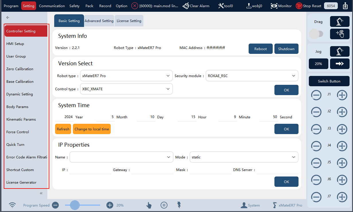
When switching between different functions through the top status bar, such as programming, settings, and communication, the left sidebar will display the corresponding submenu items for each function.
|
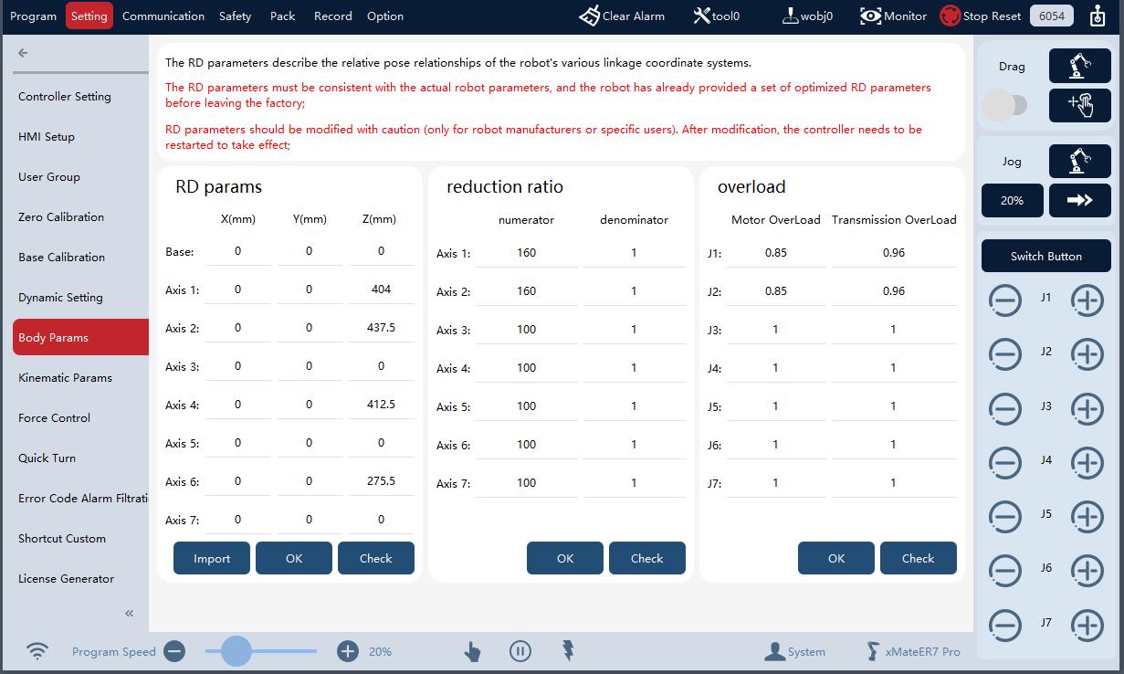
After clicking "Settings" on the top status bar, the left sidebar displays all the "Settings" submenu items. |
|
After clicking "Body Parameters", the "Body Parameters" setting page is accessed. |
|
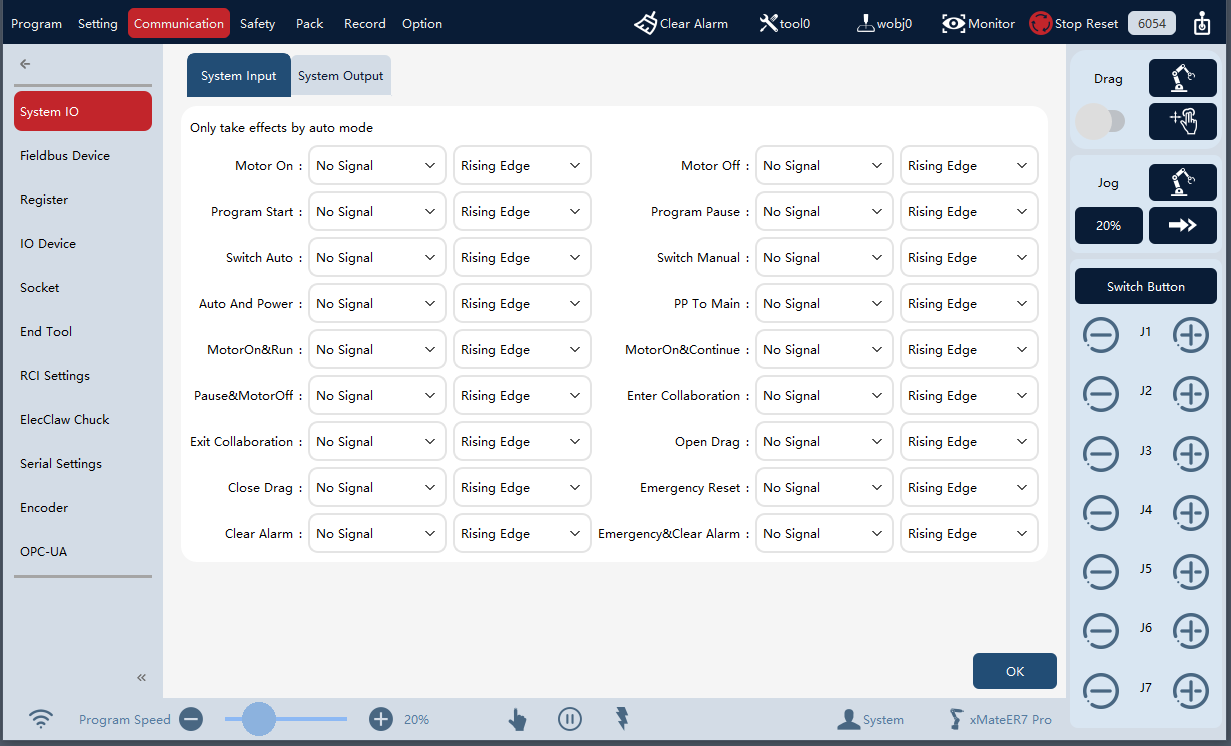
After clicking "Communication" on the top status bar, the left sidebar displays all the "Communication" submenu items. |
|
After clicking "Settings" on the top status bar again, the left sidebar displays all "Settings" submenu items, and the middle interface displays the "Body Parameters" page accessed last time by default. |
6.4.3 Right operation interface
You can click  or
or  on the top status bar to open the operation interface, which can be used to change the robot control mode, control robot motion, and perform pose teaching.
The robot supports two types of pose teaching: Jog mode and Drag mode (for cobots only). Jog mode, in which the robot is controlled to move in the corresponding direction through the Jog button. Drag mode, in which the robot motion is directly and manually guided by using the end-effector drag Pilot/xPanel handle.
|
|
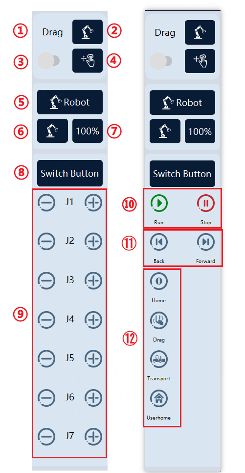
Operation interface of 7-axis robots |
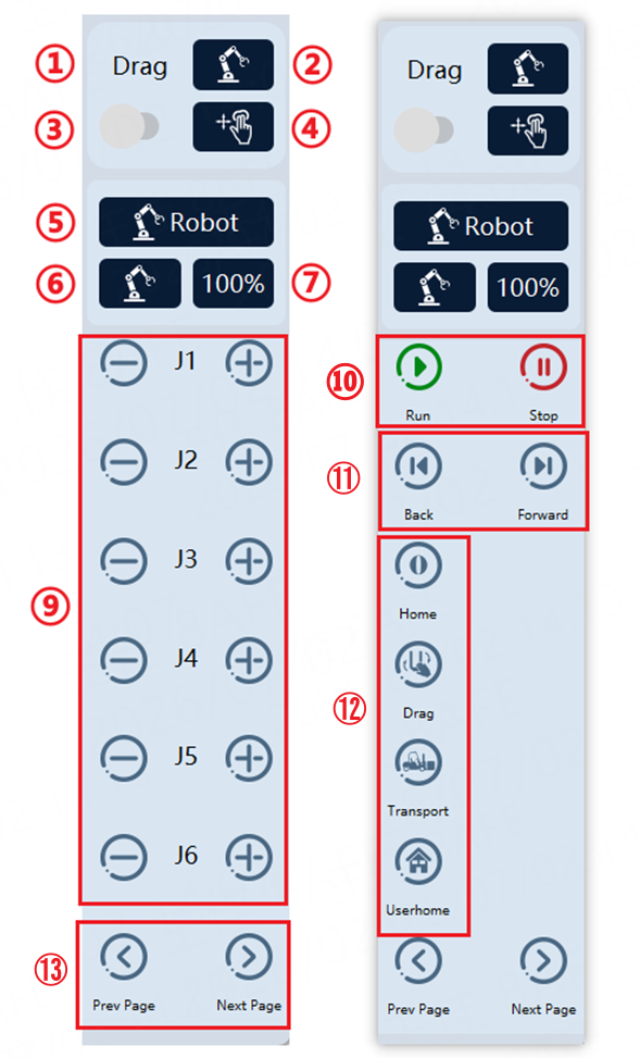
Operation interface of 6-axis or below robots |
① |
Drag settings zone, indicating that ②, ③, and ④ are drag-related options. |
② |
Drag space setting: joint space drag and Cartesian space drag. |
③ |
Drag enabling switch: turn on/off Drag mode. |
④ |
Drag mode setting: For joint space drag, only free drag is available. |
⑤ |
Jog settings zone, indicating that ⑥ and ⑦ are Jog-related options. |
⑥ |
Jog reference system setting. It is used to select the single axis mode and Cartesian mode during Jog, as well as the reference frame in Cartesian mode, including: world frame, base frame, flange frame, tool frame, and work object frame. |
⑦ |
Jog speed setting. Set the robot Jog speed between 1% and 100% (expressed in a percentage relative to the top Jog speed limit of 250 mm/s). |
⑧、⑬ |
Switch function area. Switch between the Jog button and buttons ⑩, ⑪, and ⑫. |
⑨ |
Jog button. For a 7-axis robot, J1 to J7 are displayed in the case of joint space Jog and X/Y/Z/A/B/C and Elbow in the case of Cartesian space Jog. For a 6-axis robot, J1 to J6 are displayed in the case of joint space Jog and X/Y/Z/A/B/C in the case of Cartesian space Jog. |
⑩ |
Program start/stop button. |
⑪ |
Previous (not supported yet)/next program running buttons. |
⑫ |
Shortcut button area. It allows you to configure the shortcut functions of the buttons in the custom button interface. The default configuration includes four buttons: Initial Pose, Drag Pose, Shipping Pose, and User Pose. |
|
It is important to make sure that the robot is currently in manual mode and powered off before performing Jog and turning on the Drag enabling switch. It is not allowed to start the program when the register with the pause function or system IO has not been reset. |
6.4.4 Bottom status bar
The bottom status bar displays the connection status between Robot Assist and the robot, program running speed, robot operating mode, robot status, motor status, current user login information, and robot model.

① |
Connection status between the RobotAssist software and the robot. Click this button to open the connection setting page of the robot.
The icon |
② |
Program running speed adjustment control, used to adjust the RL program running speed, with an adjustable range of 1%−100%. This parameter independently affects the program running speed in both manual and automatic modes. The program speed (-/+ 1%) can be fine-tuned by using the slider or clicking buttons "-/+". |
③ |
Robot operating mode is divided into manual and automatic modes, which are described in more detail in the chapter "Basic Operation of the Control System". |
④ |
Robot state, including the following specific states. |
|
|
|
|
|
|
|
|
|
|
|
|
|
|
|
|
|
|
|
|
⑤ |
|
⑥ |
|
|
|
|
|
|
|
|
|
⑦ |
Current login user information: Operator, Teacher, Programmer, Admin, and System. Click the button to go to the user login interface. |
⑧ |
Robot model information. |


6.5 Status monitoring
Click the "Status Monitoring" button on the top status bar to open the floating status monitoring interface. Through the status monitoring interface, the following items can be monitored: robot 3D model, task running status, IO signal, network connection status, register variables, conveyor belt status, and PERS variable information, which is convenient for users to quickly understand the robot status.
6.5.1 3D model monitoring
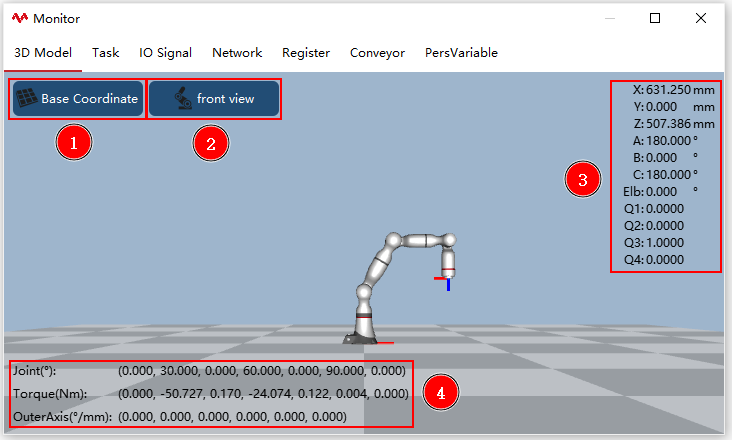
The interface visually displays the current state of the robot in the form of a 3D model. The 3D model’s viewpoint can be switched by clicking and dragging, and the model can return to the default viewpoint by clicking the "Front view" button.
① |
Frame switching: selectable base frame/world frame/work object frame. The base frame may not coincide with the world frame when the robot is not installed upright or when a group of robots is used. |
② |
Front view: Click the "Front view" button to return the model to the default viewpoint. |
③ |
End-effector pose: The position and orientation (RPY or quaternion) of the robot end-effector relative to a certain frame (work object frame, base frame, and world frame). |
④ |
Joint angle and joint torque. |
|
At present, only RobotAssist on PC supports 3D model display, and only status data can be displayed on xPad2. |
6.5.2 Task monitoring
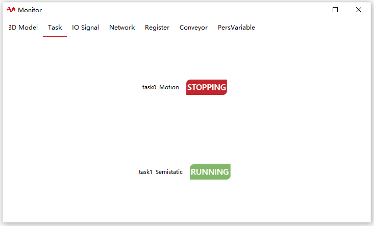
This interface displays the task name, task type, and running status of each task in the current project.
6.5.3 IO signal monitoring
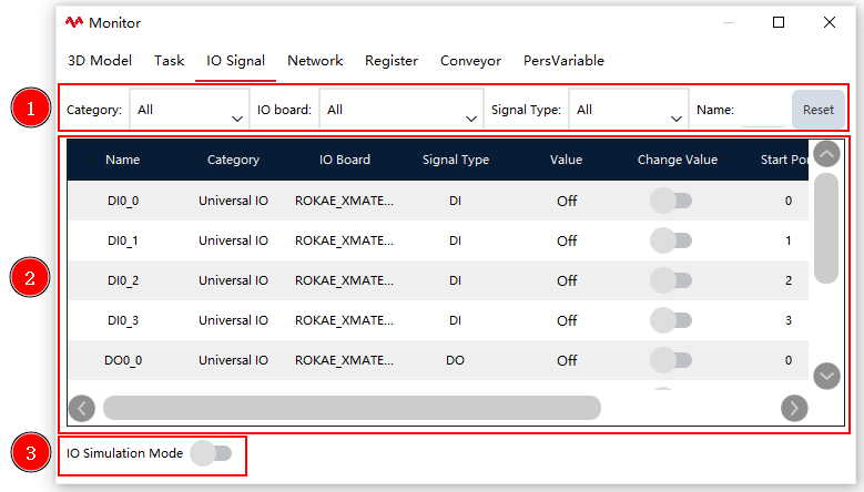
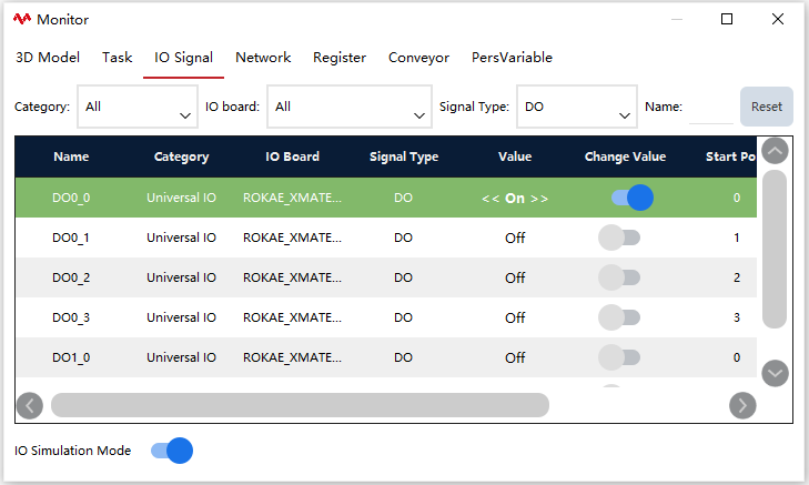
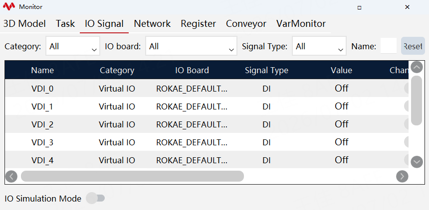
For xMate cobots, the IO signal monitoring interface displays the 4-channel DI and DO signals on the robot base and the 2-channel DI and DO signals at the end-effector by default.
For industrial robots, the IO signal monitoring interface displays configured IO signals in the controller by default.
① |
Filter, used to filter the displayed IO. The selectable filter conditions include category, IO board, signal type, and name. Click the "Reset" button to reset the filter conditions |
② |
IO signal list |
③ |
Open IO Simulation mode to simulate DI signal value |
Operating steps of IO Simulation mode:
| Step | Graphical Representation | Explanation |
|---|---|---|
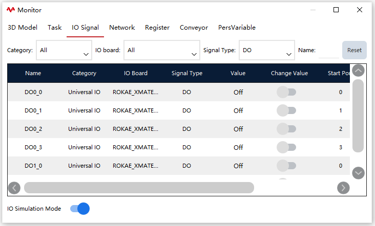
1. Go to the IO Signal page and click the [IO Simulation Mode] enabling switch to activate Simulation mode. |
|
The Simulation mode has access restrictions and requires Operator-level or higher permissions for use. |
2. Click the DI/DO value buttons to start the simulation. |
|
Note that even not in the Simulation mode, DO can also be forced to output. |
3. Click the [IO Simulation Mode] button to turn off the Simulation mode. |
|
The actual value and the modified value button are not strongly correlated, and the modified value button will be set to false after the simulation Mode is turned off. |
6.5.4 Network connection monitoring
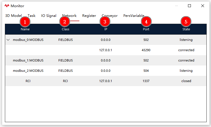
This interface displays the network information that is currently connected with the controller, including: name, type, IP, port, and status.
① |
Name: MODBUS, RCI, and SYS_SOCKET are system default unique names. User-defined names are displayed for new connections. |
② |
Type: The connection status of MODBUS, RCI, and SOCKET can be displayed. Corresponding connections can be added and configured in the relevant interface. SYS_SOCKET refers specifically to the connection of external communication. |
③ |
IP: For a client-side connection, the IP address of the target server is displayed. For a server-side connection, its own IP address is displayed. |
④ |
Port: For a client-side connection, the port number of the target server is displayed. For a server-side connection, its own port number is displayed. |
⑤ |
Status: Generally, there are three types of connection status: Connected, Disconnected, and Connecting. For a server-side connection, it displays Monitoring when it is disconnected. |
6.5.5 Register monitoring
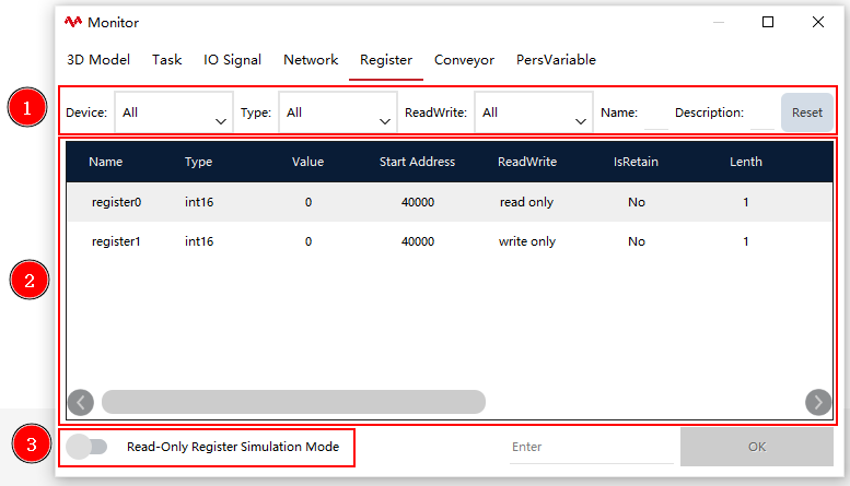
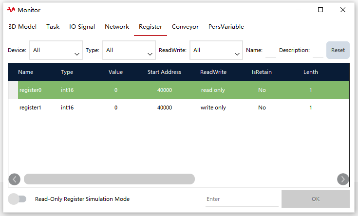
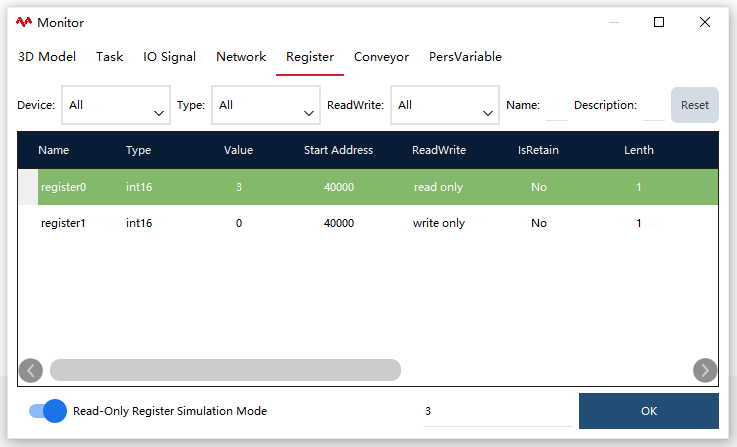
This interface displays the information of each register. If you think that there are too many registers displayed by default, you can filter them. The selectable filter conditions include: device, type, read-write, name, and description. Click the "Reset" button to update them.
① |
Filter: Used to filter the displayed registers. |
② |
Register signal list. |
| Step | Graphical Representation | Explanation |
|---|---|---|
Write-only register assignment: Select the write-only register, enter the expected value in the input box to the left of the "Write" button, and click the "Write" button to change the current value of the register. |
|
1. Users with the permission level of Operator are not allowed to perform writing; |
Read-only register assignment: Enable the "write-only register stimulation mode", enter the expected value in the input box to the left of the "Write" button, and click the "Write" button to change the current value of the register. |
|
6.5.6 Conveyor belt monitoring
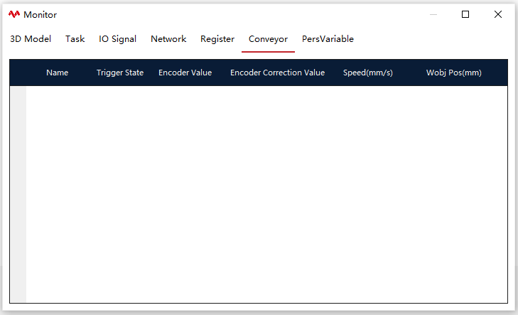
Used to cooperate with the conveyor belt process package and monitor the status of conveyor belt. See the conveyor belt tracking process package for details.
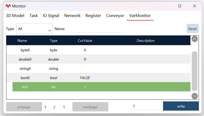
6.5.7 Variable monitoring
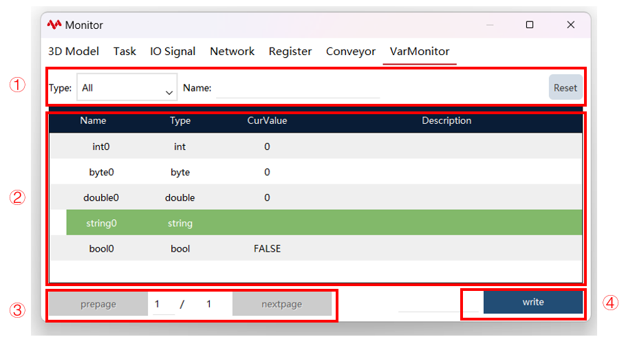
This interface displays the real-time information of variables listed in the variable list.
① |
Filter: Filter according to class insertion type and name filter. Note: Currently, variable monitoring supports only the monitoring of individual variables or arrays of the following types: bool, int, double, byte, and string. |
② |
Monitor the variable list. |
③ |
Previous/Next: Only up to 10 variables can be monitored per page. |
④ |
Write button: Assign the variables. |
| Step | Graphical Representation | Explanation |
|---|---|---|
1. In the variable monitoring selection interface, add variables to be monitored using the "Batch Add" button or the "Single Add" button. |
|
Variable monitoring only monitors variables that exist in the selection interface |
2. Write: In the "Modified Value" column, write the value of the variable to be modified, and click "Write" button to write the value to the variable in real time. |
|
Users with the permission level of Operator are not allowed to perform writing. When modifying a non-PERS variable, clicking "PPTOMAIN" will revert the changed value of the non-PERS variable to its original state. |
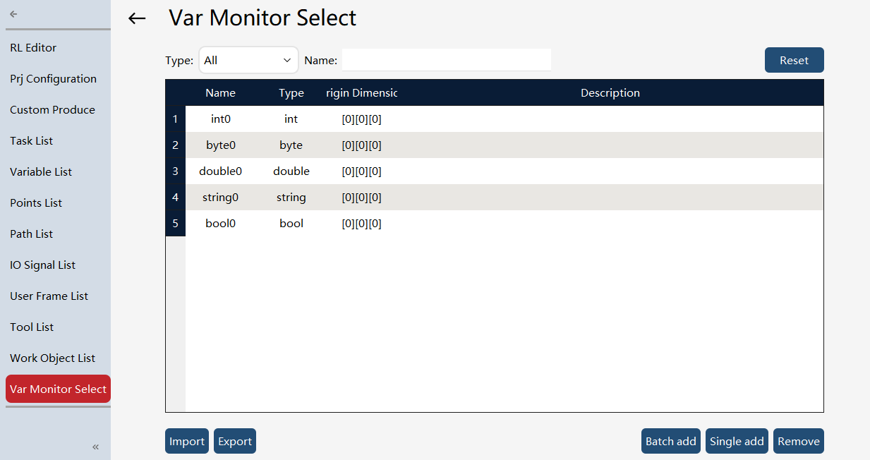
Note: After adding a new variable to be monitored, you need to first execute the "PPTOMAIN" operation before you can read or modify the variable.
6.6 Programming module overview
RL editor |
Mainly used for writing and debugging RL programs. |
Project configuration |
Used for operations such as project creating, loading, import and export, and push. |
Custom production |
Users can customize several controls to conveniently monitor and edit registers, DI/DO signals, and project variables. |
Task list |
Used for viewing, creating, editing, and importing and exporting tasks. |
List of variables |
Used for viewing, creating, editing, and importing and exporting variables. |
Point list |
Used for viewing, creating, editing, and importing and exporting points. |
Path list |
Used for viewing, creating, editing, and importing and exporting paths. |
IO signal list |
Used for viewing, creating, editing, and importing and exporting IO signals. |
User frame list |
Used for viewing, creating, editing, and importing and exporting user frames. |
Tool list |
Used for viewing, creating, editing, and importing and exporting tool frames. |
Work object list |
Used for viewing, creating, editing, and importing and exporting work object frames. |
Variable monitoring selection interface |
In the variable monitoring selection interface of status, you can perform the following operations on monitored variables: import, export, batch add, single add, and deletion. |
6.7 Setting module overview
Controller settings |
Controller system-related setting interface, including robot type, system time, and system IP. |
HMI settings |
HMI-related settings, including language switching and Teach Pendant IP settings. |
User group |
User management, including login and password management. |
Calibration |
Perform robot zero calibration, force sensor calibration, soft calibration, and base frame calibration |
Frame calibration |
Set the global tool, global work object, and global user frames. |
Dynamic settings |
Robot dynamics-related settings. |
Body parameters |
Robot kinematics-related settings, such as RD parameters, reduction ratio, and overload coefficient. |
Motion parameters |
Acceleration and deceleration performance, safety control, and other settings for the robot. |
Force control parameters |
Force control-related settings for the robot. |
Quick adjustment |
Quick orientation adjustment settings. |
Electronic nameplate |
Electronic nameplate-related settings. (This function is only supported by some models) |
Error code alarm filtering |
Error code alarm filtering-related settings. |
Custom buttons |
Custom button binding functionality. |
6.8 Communication module overview
System IO |
System input and system output signal settings. |
Cross-connection |
Cross-connection settings for IO and registers. |
External communication |
External communication interface settings based on the Socket. |
Register |
Register-related settings. |
IO device |
IO device settings. |
Bus devices |
Configure various bus expansion modules. |
RCI settings |
RCI communication settings. |
xPanel settings |
CR robot xPanel settings. |
Electric gripper and suction cup |
Settings and tests of all kinds of electric grippers and suction cups. |
Serial port settings |
Serial port-related settings. |
Encoder |
Encoder settings required for conveyor belt tracking function. |
OPC-UA |
OPC-UA-related settings. |
6.9 Safety module overview
Joint limit |
Robot joint limit settings. |
Robot limits |
Robot speed, reduced mode speed, power, and momentum settings. |
Virtual wall |
Virtual wall-related settings. |
Collision detection |
Collision detection-related settings. |
Safe region |
Safe region-related settings. |
Safety position |
Safety position-related settings. |
Safety DO settings |
Safety DO-related settings. |
6.10 Process package module overview
Support stacking, tray, conveyor belt tracking, PV typesetting, PV inserting, and other process packages. Please refer to the corresponding chapters.
6.11 Log module overview
HMI logs |
Display the current operation interface log information. |
Controller logs |
Display the running log of the controller connected to the robot. |
Operation logs |
Display logs related to robot operation. |
Log timeline |
Display the log history visually through a timeline. |
Internal logs |
Used to display the underlying log information of the Teach Pendant or RobotAssist. |
Diagnostic setting |
Used to assist developers in problem diagnosis. |
Hardware status |
Add display of health monitoring information for the IPC and teach pendant. |
Diagnostic data monitoring |
Supported only on the PC HMI; this feature allows the use of condition verification function. It is unavailable on the teach pendant. |
6.12 Option module overview
Connect |
RobotAssist software and controller connection, related operations and settings. |
About ROKAE |
Version information and company profile. |
Software upgrade |
Control system software upgrade and backup related operations. |
Export |
Control system configuration export. |
Import |
Control system configuration import. |
File manager |
Several folders involved in the RobotAssist software. |
Demos |
Demonstration of some features. |