5.1 Introduction to this chapter
ROKAE has several series of robots. This chapter mainly introduces the system structure and connection mode of different series of robots to deepen users' understanding of robot systems.
Users can optionally read the contents of this chapter based on the model they use.
5.2 Control system structure
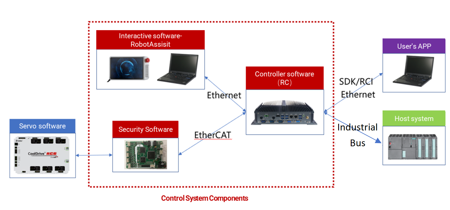
xCore control system is based on CS architecture, including HMI software (RobotAssist) and controller software RC.
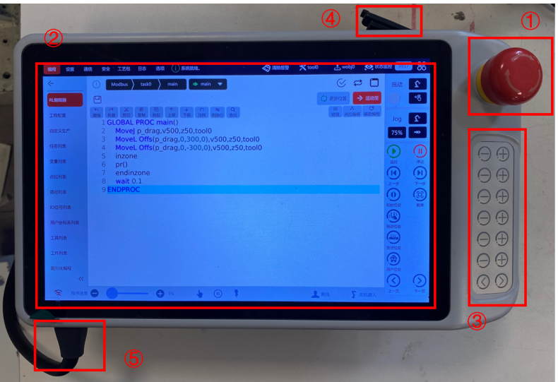
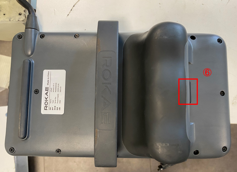
5.3 Industrial robot system composition
This chapter mainly introduces the structure, wiring, and power-on start-up methods of industrial robots. There may be certain differences in the robot body and control cabinet depending on the robot’s specific model. For more information, please refer to the XBC5 Series Controller (xCore System) Product Manual.
The main structure and wiring relations of an industrial robot system are shown in the figure below, mainly including: robot body, Teach Pendant, control cabinet, relay cable, and power cord.
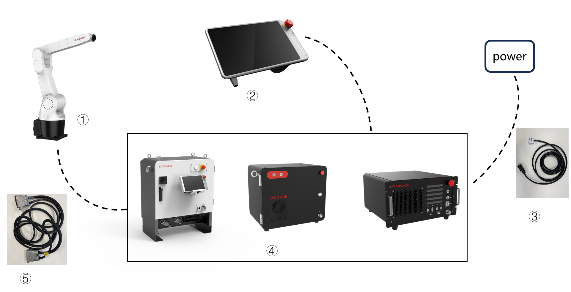
① |
Robot body; |
② |
Teaching pendant; |
③ |
Power cable; |
④ |
Control cabinet; |
⑤ |
Connecting cable, for connecting with control cabinet or robot; |
5.3.1 XBC5 series controller introduction
XBC5 series control cabinets include three models: XBC5, XBC5-E, XBC5-M.
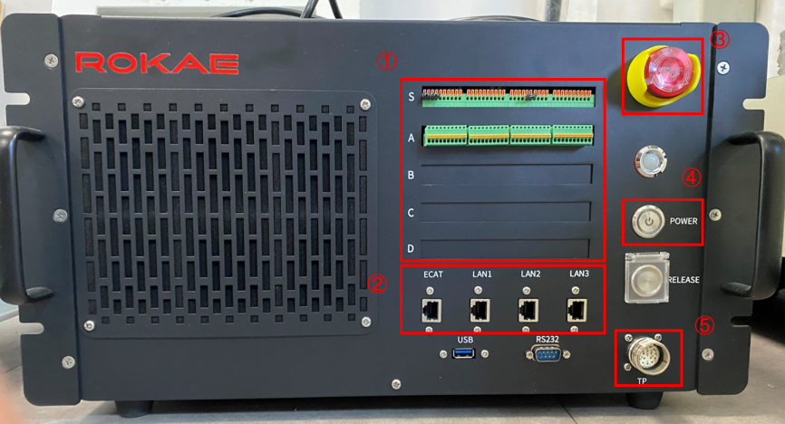
Taking XBC5-M as an example, the main components and functions of the cabinet are briefly introduced, to which other models are similar in components and functions.
① |
Security/Universal IO wiring terminals; |
② |
Network interface: including debugging interface, EtherCAT expansion network interface, and visual interface; |
③ |
Emergency stop switch: Used to control the motor’s band-type brake in case of emergency; |
④ |
Power switch: Used to control the startup & shutdown of the robot; |
⑤ |
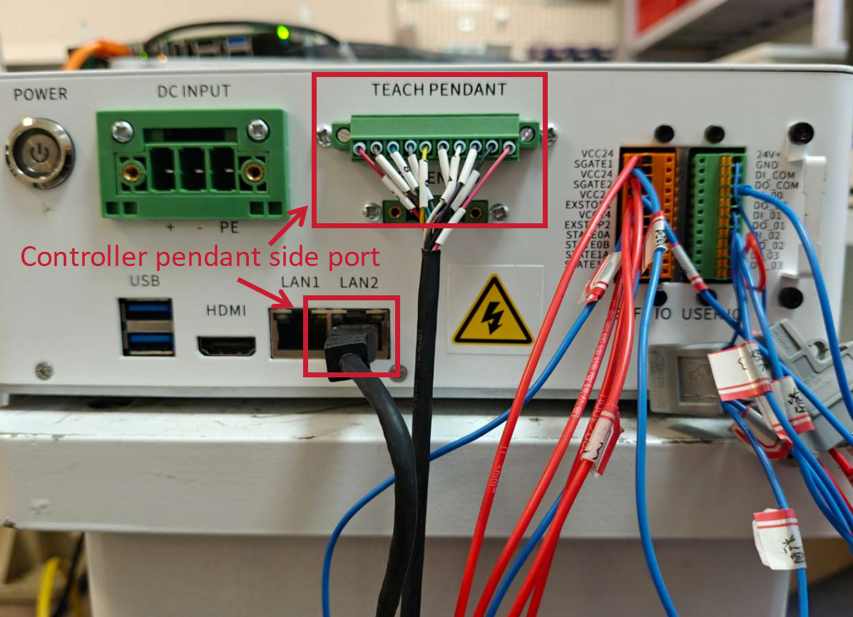
Teach Pendant wiring port: Used to connect xPad2; |
5.3.2 XBC5-M controller wiring, power-on, and start-up
| Step | Graphical Representation | Explanation |
|---|---|---|
1. Connect the robot body with the controller through the relay cable; |
|
As there is a difference between the two ends of the relay cable’s heavy-duty connector, please confirm before connecting. |
2. Connect the Teach Pendant with the controller according to the figure; |
|
|
3. Connect the power cord with the controller; |
|
The interface of the power cord on the side of the controller is designed with a buckle. |
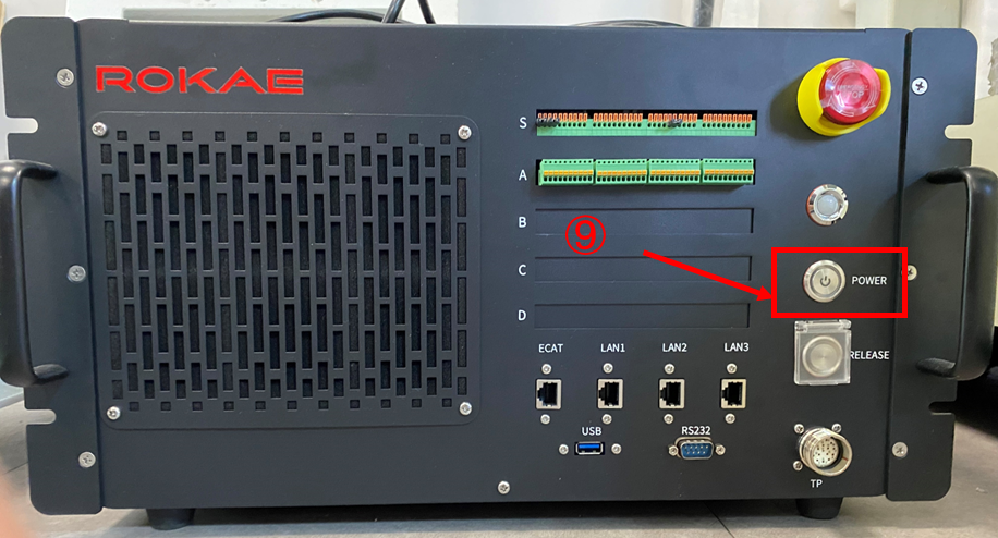
4. Start up the control cabinet after powering it on. |
|
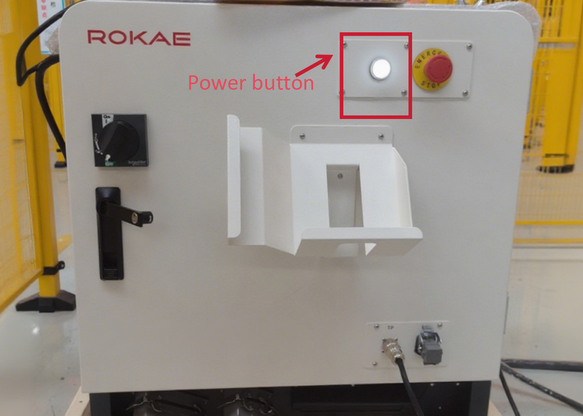
After the power cord is powered on and the POWER button is pressed, the xPad2 Teach Pendant will automatically start up. |
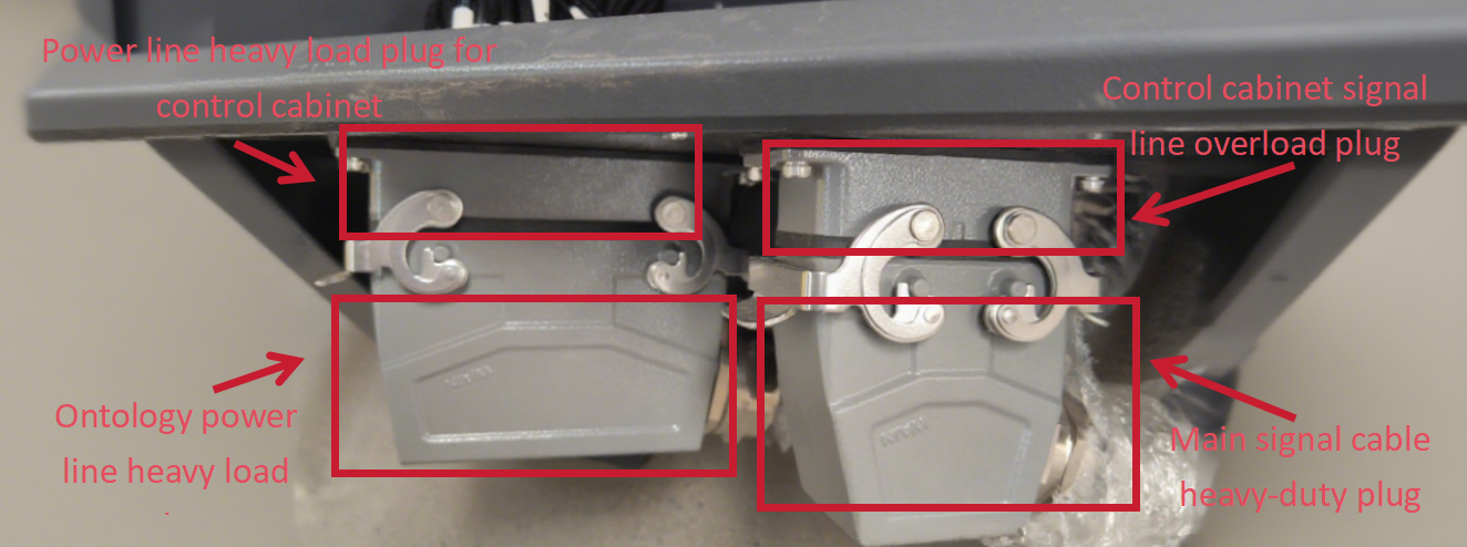
① |
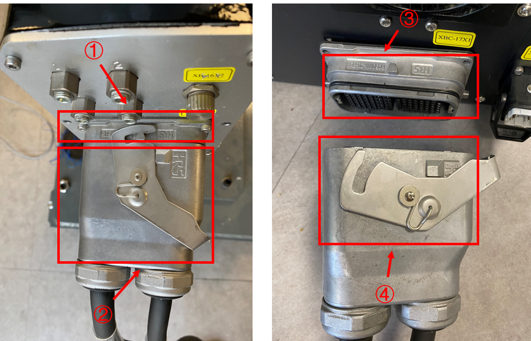
Robot body side loading plug; |
② |
Trunk side load plug; |
③ |
Control cabinet side load plug; |
④ |
Trunk side load plug; |
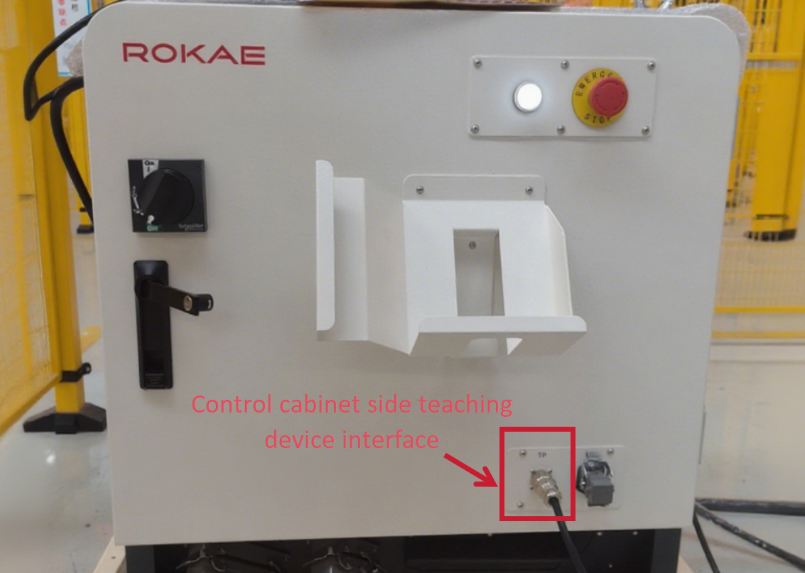
⑤ |
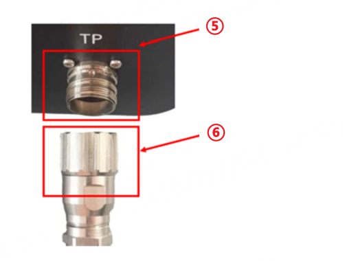
Control cabinet side teaching pendant connection port; |
⑥ |
Teach pendant side connection port; |
⑦ |
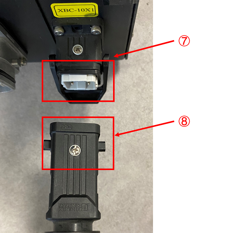
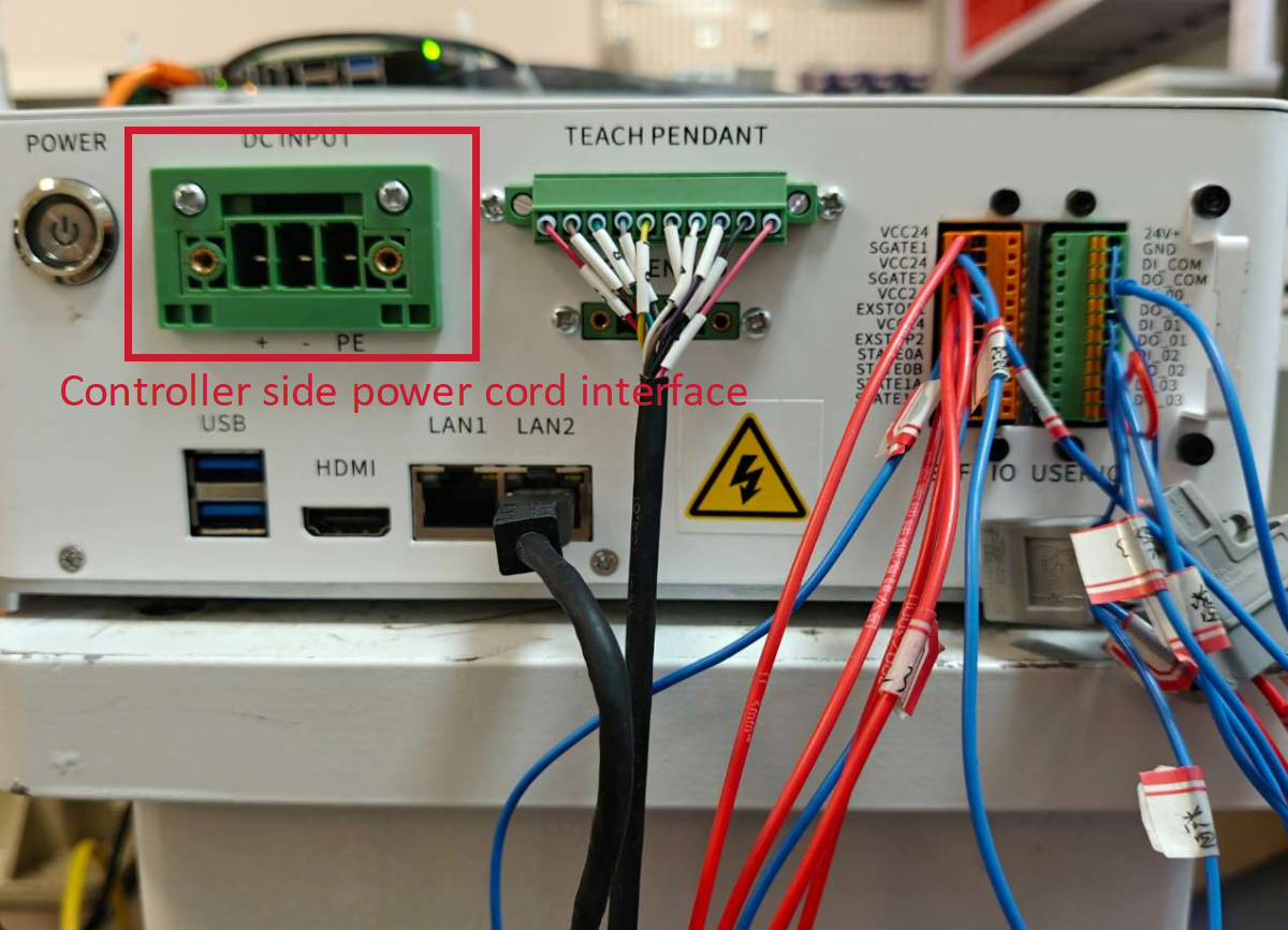
Control cabinet side power cord connection port; |
⑧ |
Power cord side connection port; |
⑨ |
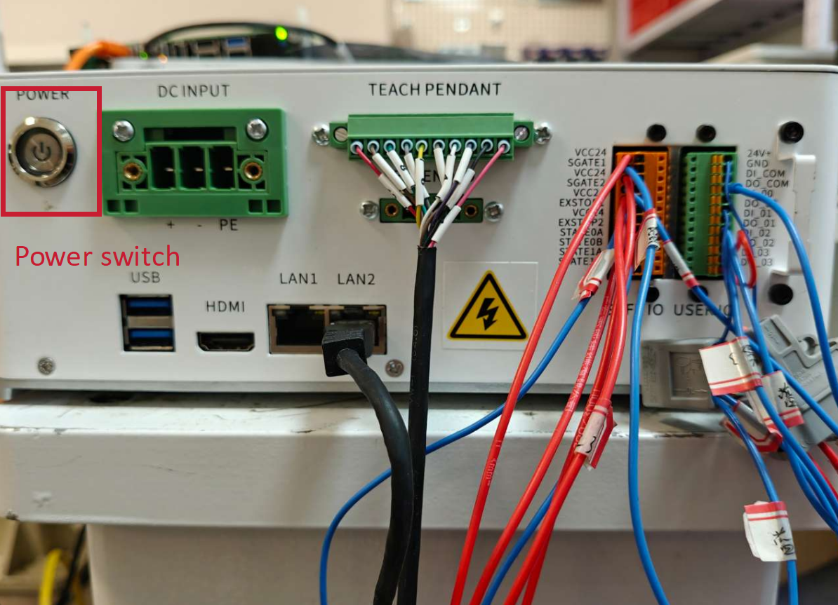
Power button; |
5.3.3 XBC5 controller wiring, power-on, and start-up
| Step | Graphical Representation | Explanation |
|---|---|---|
1. Connect the robot body with the controller through the relay cable; |
|
The power cord and relay cable on the controller side are designed as integrated units respectively, eliminating the need for additional installation. |
2. Connect the Teach Pendant with the controller according to the figure; |
|
|
3. Start up the control cabinet after powering it on. |
|
After the power cord is powered on and the POWER button is pressed, the xPad2 Teach Pendant will automatically start up. |
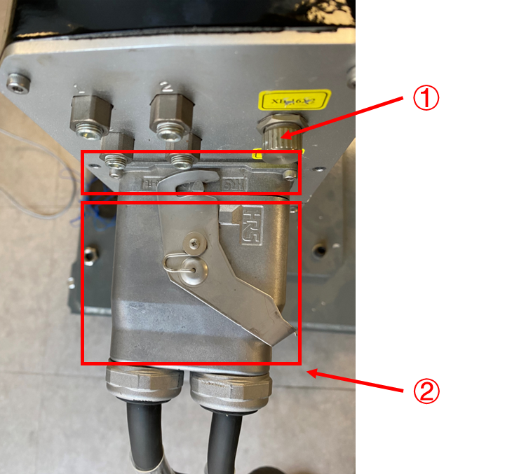
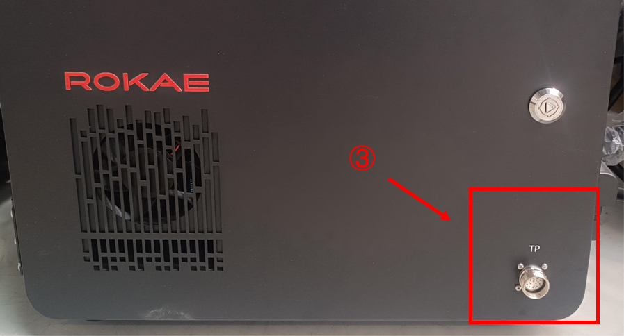
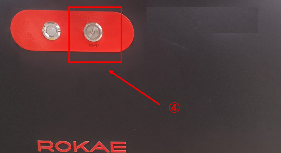
① |
Robot body side loading plug; |
② |
Trunk side load plug; |
③ |
Teach pendant side connection port; |
④ |
Power button; |
5.3.4 XBC5-E controller wiring, power-on, and start-up
| Step | Graphical Representation | Explanation |
|---|---|---|
1. Connect the robot body with the controller through the relay cable; |
|
The power cord and relay cable on the controller side are designed as integrated units respectively, eliminating the need for additional installation. |
2. Connect the Teach Pendant with the controller according to the figure; |
|
|
3. Start up the control cabinet after powering it on. |
|
After the power cord is powered on and the POWER button is pressed, the xPad2 Teach Pendant will automatically start up. |
5.4 Collaborative robot system composition
5.4.1 ER and ER PRO
ER and ER PRO series are designed without a controller, and their system composition is shown in the figure below.
Attention: ER series robots do not support xPad2 Teach Pendant.
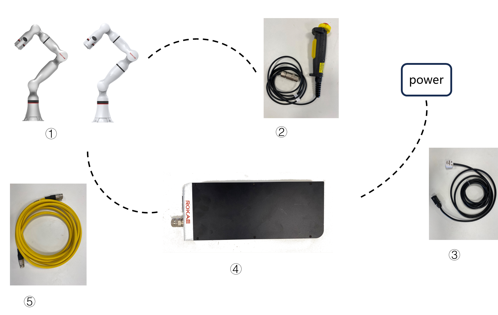
① |
Robot body; |
② |
Handheld enable; |
③ |
Power cable; |
④ |
Transformer; |
⑤ |
Connecting cable, for connecting with control cabinet or robot; |
For ER series robots, you can refer to the following steps for connection and power-on.
| Step | Graphical Representation | Explanation |
|---|---|---|
1. Connect the robot body with the power adapter through the relay cable; |
|
|
2. Connect the handheld enabling device. |
|
|
3. Connect the power cord. |
|
|
4. Connect HMI. |
|
As ER series robots do not support connecting Teach Pendant, please connect via PC. See below for details. |
5. Connect the power supply, and press the power adapter [switch] and the robot body power supply [switch] in sequence. |
|
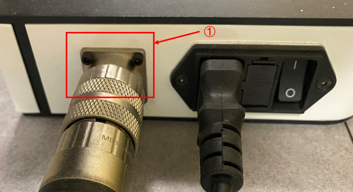
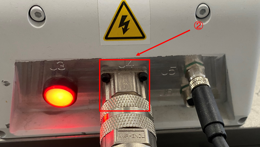
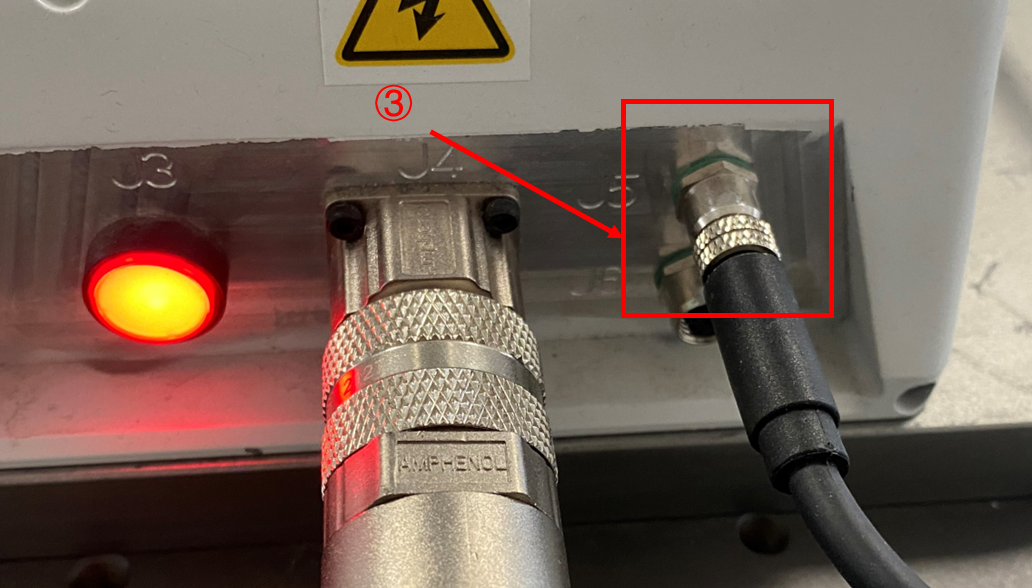
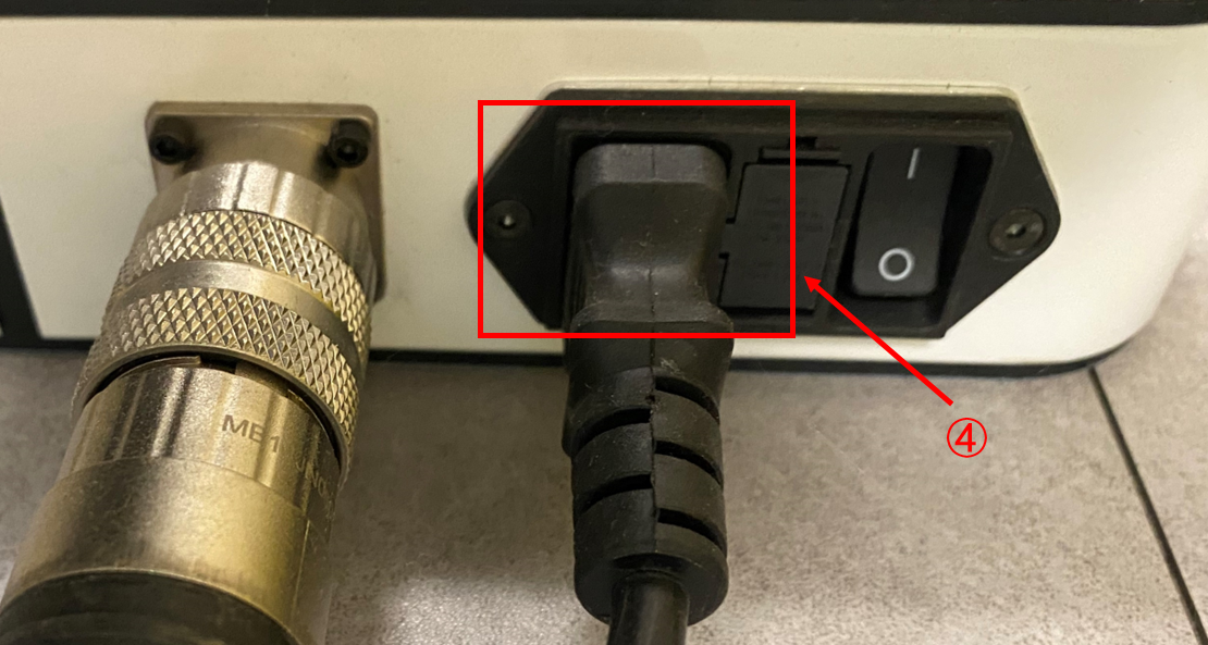
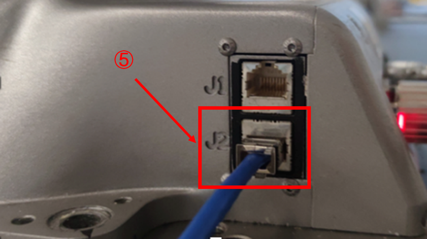
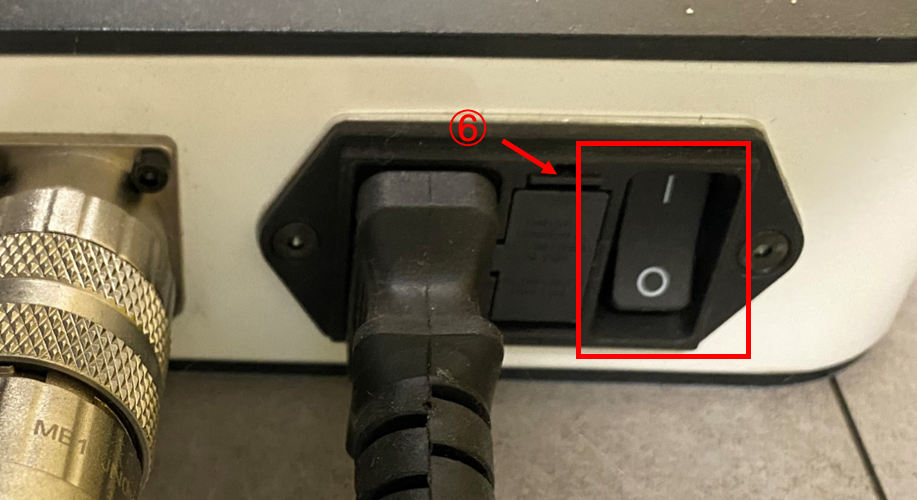
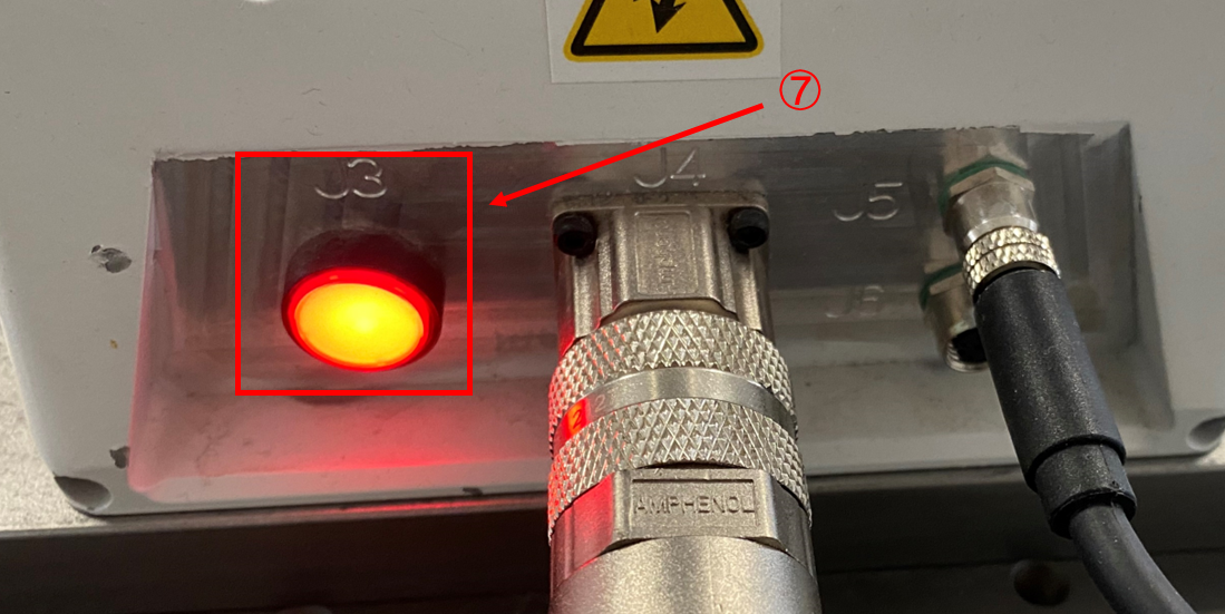
① |
Power adapter side trunk port; |
② |
Robot body side trunk line port; |
③ |
Handheld enable port on the side of the robot body; |
④ |
Power cord port on power adapter side; |
⑤ |
Network cable port; |
⑥ |
Power adapter switch; |
⑦ |
Robot body switch; |
5.4.2 CR and SR
CR and SR series collaborative robots are designed without a controller, and their system composition is shown in the figure below.
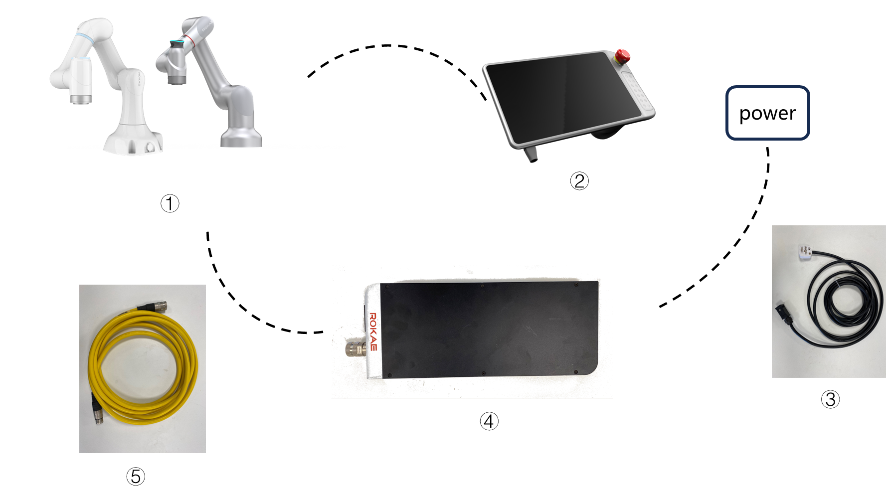
① |
Robot body; |
② |
Teaching pendant; |
③ |
Power cable; |
④ |
Transformer; |
⑤ |
Connecting cable, for connecting with control cabinet or robot; |
For CR series robots, you can refer to the following steps for connection and power-on. SR series is similar to CR series in connection and power-on.
| Step | Graphical Representation | Explanation |
|---|---|---|
1. Connect the robot body with the power adapter through the relay cable; |
|
|
2. Connect the Teach Pendant; |
|
|
3. Connect the power cord; |
|
|
4. Connect the power supply, and press the power adapter [switch] and the robot body power supply [switch] in sequence. |
|
After the robot is started up, the Teach Pendant will be automatically started up. |
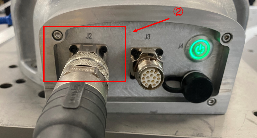
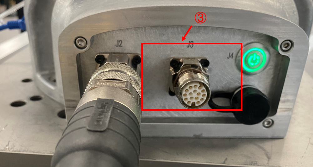
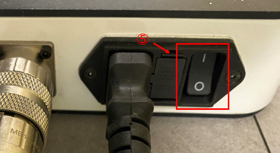
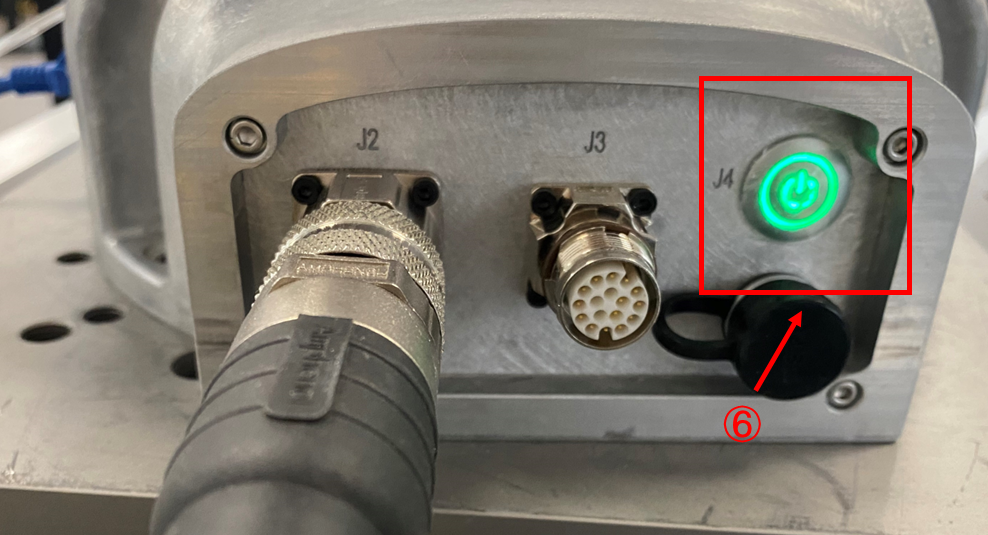
① |
Power adapter side trunk port; |
② |
Robot body side trunk line port; |
③ |
Handheld enable port on the side of the robot body; |
④ |
Power cord port on power adapter side; |
⑤ |
Power adapter switch; |
⑥ |
Robot body switch; |
5.4.3 CR-C and SR-C
CR and SR series collaborative robots are designed with a controller, and their system composition is shown in the figure below.
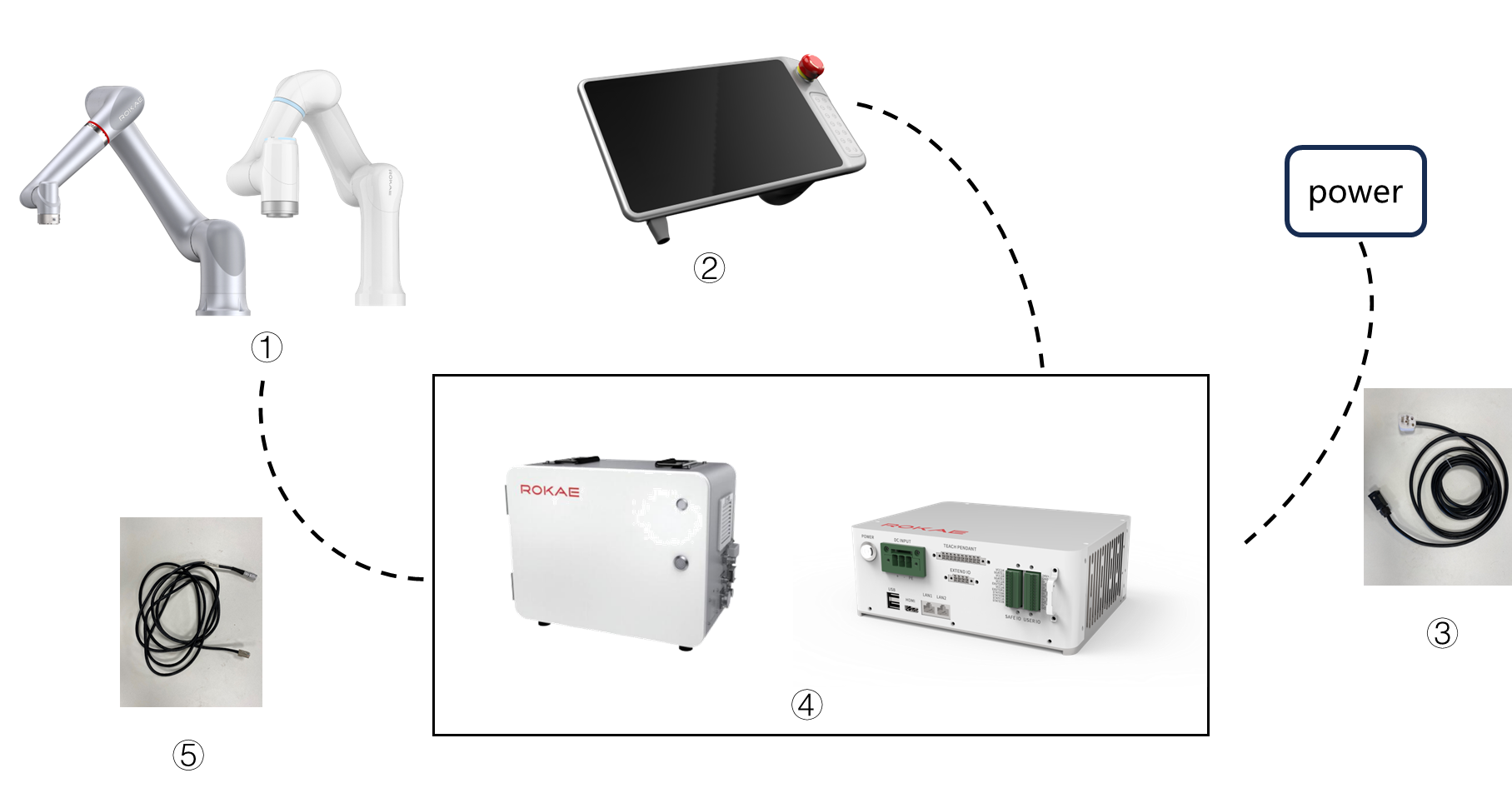
① |
Robot body; |
② |
Teaching pendant; |
③ |
Power cable; |
④ |
Control cabinet; |
⑤ |
Connecting cable, for connecting with control cabinet or robot; |
5.4.3.1 SR-C controller and its wiring, power-on and start-up
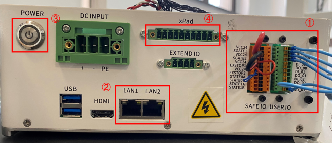
① |
Security/Universal IO wiring terminals; |
② |
Network interface: including debugging interface and visual interface; |
③ |
POWER switch: Used to control the power on/off state of the robot; |
④ |
Teach Pendant wiring port: used to connect xPad2. |
| Step | Graphical Representation | Explanation |
|---|---|---|
1. Connect the robot body with the controller through the relay cable; |
|
As there is a difference between the two ends of the relay cable’s heavy-duty connector, please confirm before connecting. |
2. Connect the Teach Pendant with the controller according to the figure; |
|
|
3. Connect the power cord with the controller; |
|
The interface of the power cord on the side of the controller is designed with a buckle. |
4. Start up the control cabinet after powering it on. |
|
After the power cord is powered on and the POWER button is pressed, the xPad2 Teach Pendant will automatically start up. |
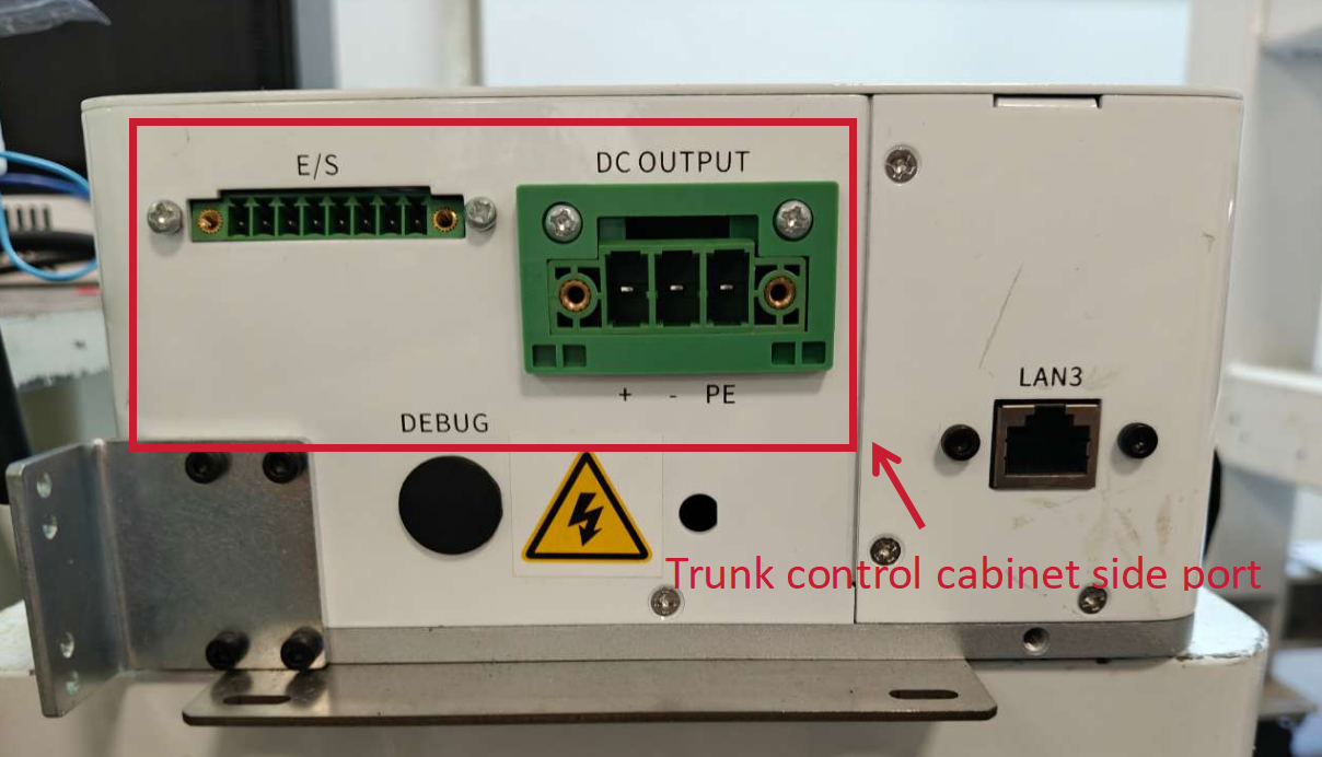
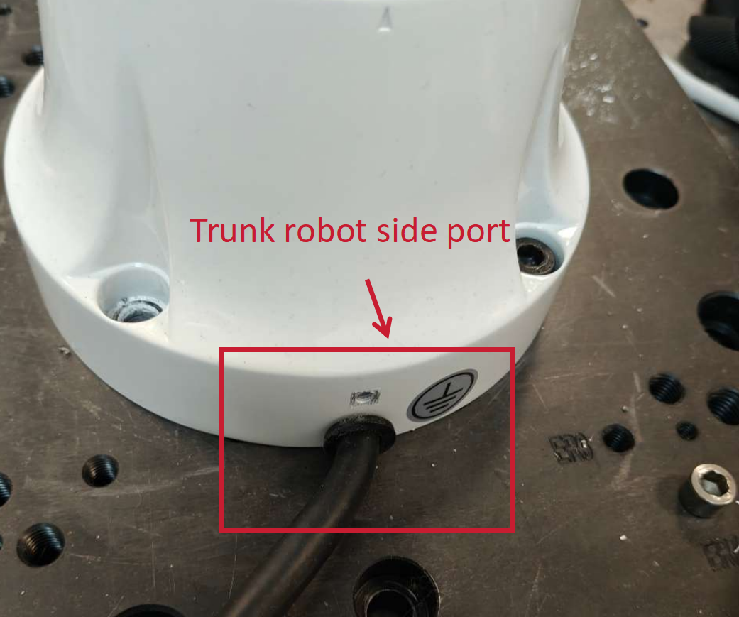
5.4.3.2 CR-C controller and its wiring, power-on, and start-up
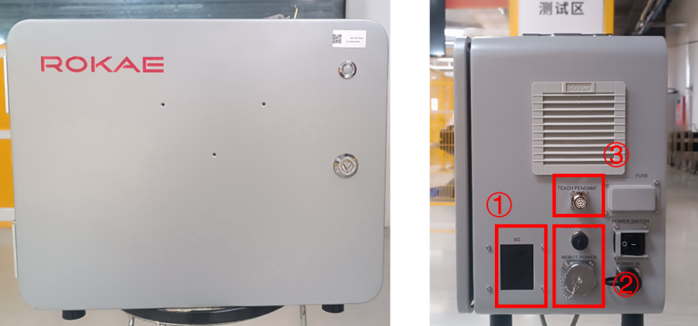
① |
Security/Universal IO wiring terminals; |
② |
Realy cable interface: Used to connect the robot and controller; |
③ |
Teach Pendant wiring port: Used to connect xPad2 |
| Step | Graphical Representation | Explanation |
|---|---|---|
1. Connect the robot body with the controller through the relay cable; |
|
Note that the CR-C series controller has two relay cables: relay power cord and relay signal cable. |
2. Connect the Teach Pendant with the controller according to the figure; |
|
|
3. Connect the power cord with the controller; |
|
The interface of the power cord on the side of the controller is designed with a buckle. |
4. Start up the control cabinet after powering it on. |
|
After the power cord is powered on and the POWER button is pressed, the xPad2 Teach Pendant will automatically start up. |
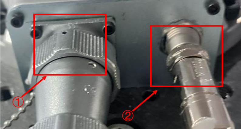
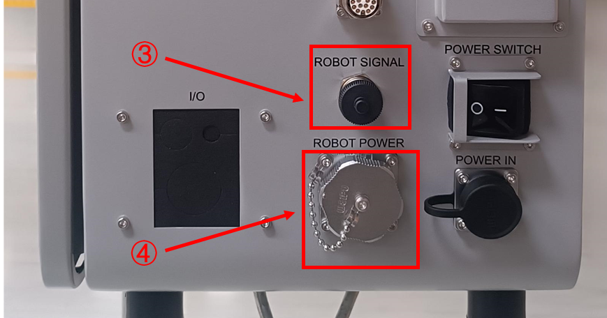
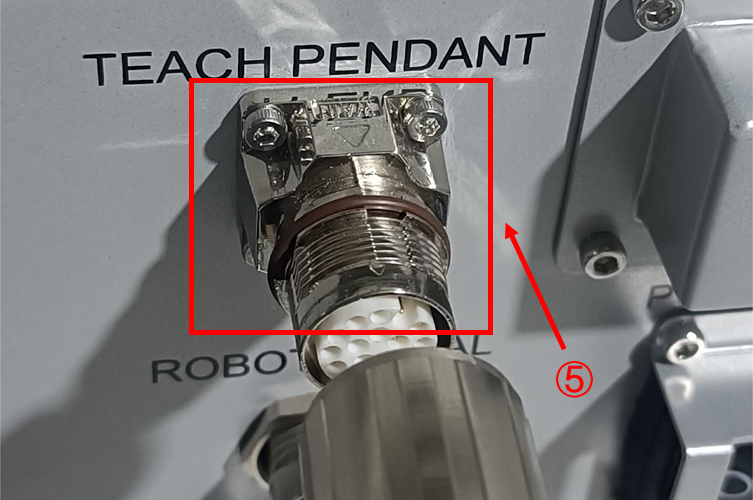
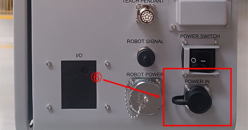
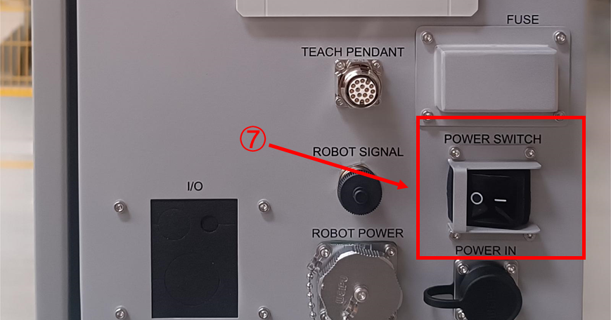
① |
Robot side relay power cord port; |
② |
Robot side relay signal line interface; |
③ |
Control cabinet side relay signal line port; |
④ |
Control cabinet side relay power cord port; |
⑤ |
Control cabinet side teaching pendant port; |
⑥ |
Control cabinet side power cord port; |
⑦ |
Power switch; |
5.5 HMI and robot connection
Robot Assist, as the host computer software of the robot, can run on PC, xPad2, and other devices. You can connect the device where the Robot Assist software is located and the robot to the same LAN (local area network) and establish a connection with the connected robot by robot detection, manually entering the controller service address, etc.
5.5.1 xPad2 and robot connection
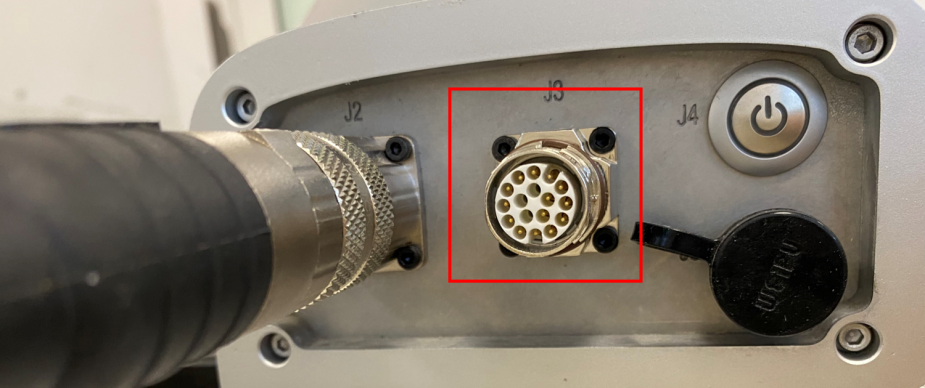
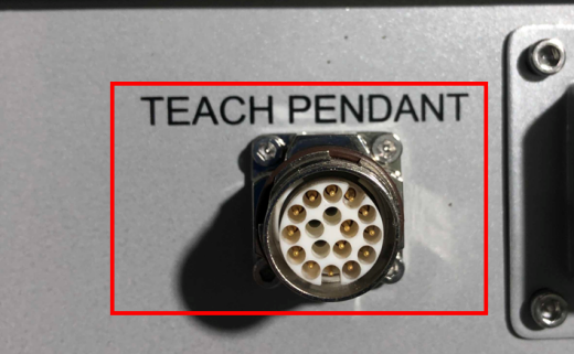
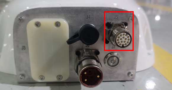
For the use of the Teach Pendant xPad2, the default network segment of the Teach Pendant is 192.168.1.X. You need to first modify the IP address of the Teach Pendant to be in the same network segment as the robot body, and then connect the xPad2 to the corresponding port of the robot;
5.5.1.1 Hardware connection
| Model | Introduction | Picture |
|---|---|---|
CR |
The xMate CR series robot xPad2 wiring port is located at the base. |
|
CR-C |
The xMate CR-C series robot xPad2 wiring port is located on the upper part of the control cabinet. |
|
SR |
The xMate SR series robot xPad2 wiring port is located at the base. |
|
SR-C |
SR special controller (need to add an adapter) |
|
XBC5 |
The XBC5 series controller xPad2 wiring port is located at the bottom of the controller. |
|
XBC5-M |
The XBC5-M series controller xPad2 wiring port is located at the bottom of the controller. |
|
XBC5-E |
The XBC5-E series controller xPad2 wiring port is located at the bottom of the controller. |
|
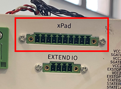
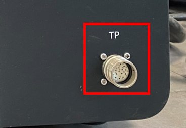
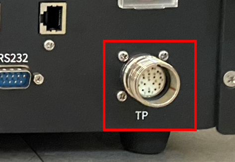
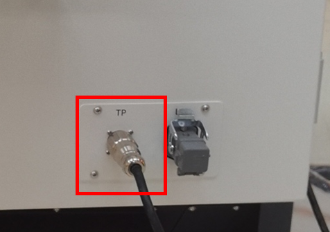
5.5.2 PC and robot connection
RobotAssist software can run on the PC, and then the PC can be connected with the robot or controller.
5.5.2.2 One-to-one HMI and robot connection
When using a PC on which Robot Assist is running to debug a robot, the PC can be directly connected to the robot via network cable (table+illustration concretization);
| Model | Introduction | Picture |
|---|---|---|
ER/ER PRO |
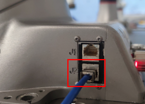
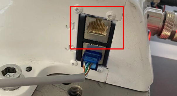
The xMate ER series cobot features two Ethernet interfaces on the base. The J2 port defaults to the fixed IP address of 192.168.0.160. |
|
CR |
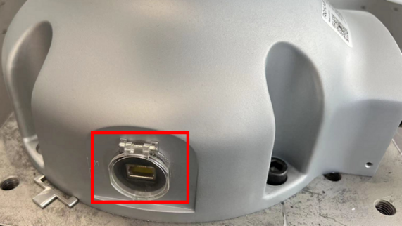
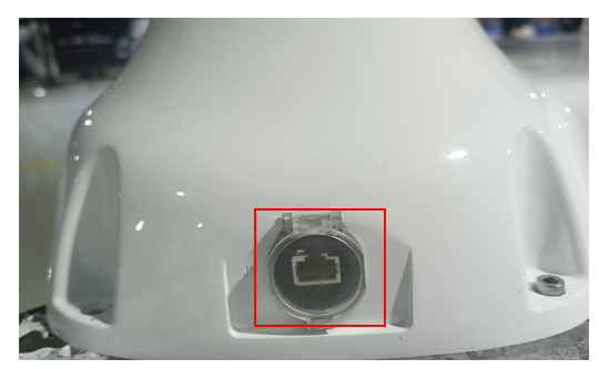
The xMate CR series cobot features only one Ethernet interface J1 (standard configuration) on the base, which defaults to the fixed IP address of 192.168.2.160. |
|
CR-C |
xMate CR has a controller |
|
SR |
xMate SR (J2 network interface) |
|
SR-C |
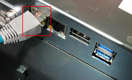
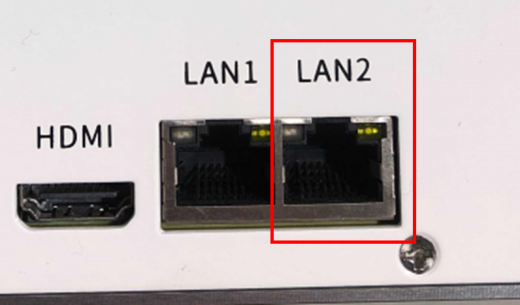
The xMate SR-C debugging network interface is LAN2, whose default IP address is 192.168. 0.160; |
|
XBC5/XBC5E |
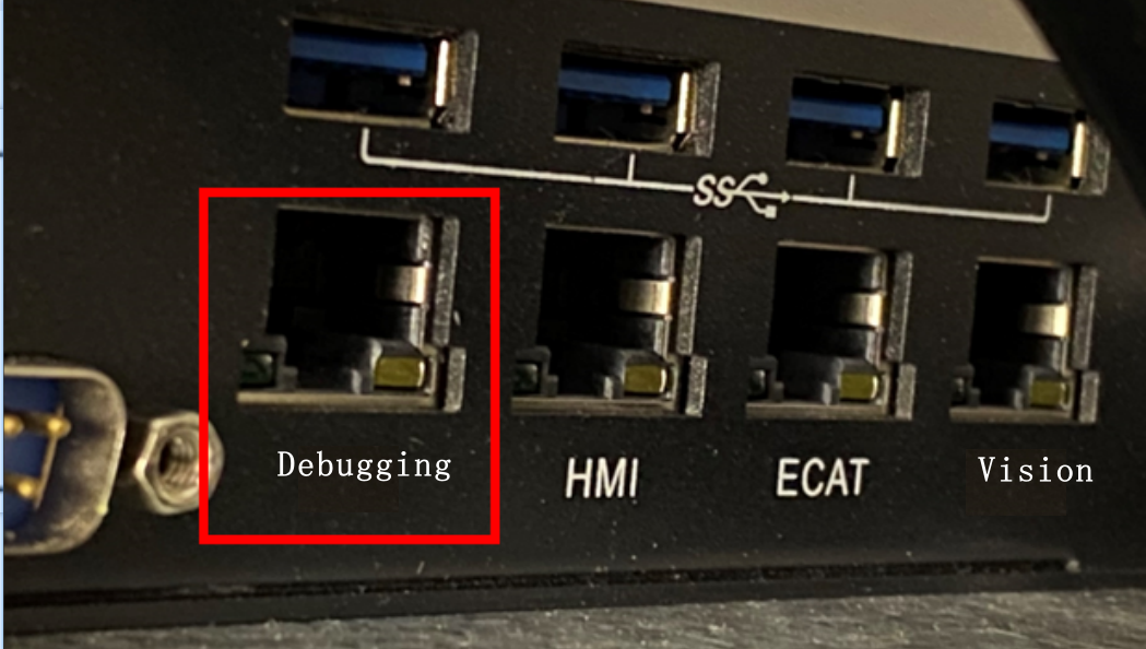
There are four Ethernet interfaces from left to right on the controller, which are: |
|
XBC5 M |
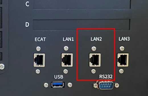
LAN2 is the debugging network interface of the XBC5 M controller, and its IP address defaults to 192.168.0.160; |
|
5.5.2.3 One-to-multiple HMI and robot connection
When switching between multiple robots, these robots can be connected to the same LAN, and the PC on which Robot Assist is running will detect the robots available for connection on the same network segment;
5.5.2.4 Wireless connection
For scenarios where a wired connection is not convenient (such as on AGVs), the robot can be connected to a wireless router via the reserved network interface (the network interface on the xMate cobot base; and the visual/debugging network interface of industrial robot controller) on the robot controller and then to the HMID wirelessly.
5.5.2.6 Direct cable connection
Both the robot base and the controller feature one network interface that defaults as the debugging network interface with the fixed IP address of 192.168.0.160. This IP address is the same for all robots and is not recommended to be modified arbitrarily. The PC on which Robot Assist is running can be connected to the network interface directly via a network cable to control the robot.
5.5.2.7 External network interface connection
External network interface connection supports two types of settings: obtain an IP address automatically or assign a static IP address.
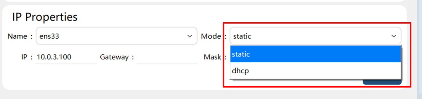
Obtain an IP address automatically — After the network interface J1 of cobots or the visual network interface of industrial robots is set to DHCP mode, and the robot is connected via the network interface to a router with DHCP, which automatically assigns an IP address to the robot, the robot can then be detected and connected via robot detection.
Assign a static IP address — After the network interface J1 of cobots or the vision network interface of industrial robots is set to the IP address in the required network segment, and the robot is connected via the network interface to a router, the robot can be visited and controlled via the robot’s IP address.
5.5.2.7.1 Direct cable connection of devices such as PC
Both the robot base and the controller feature one network interface that defaults as the debugging network interface with the fixed IP address of 192.168.0.160. This IP address is the same for all robots and is not recommended to be modified arbitrarily. The PC on which Robot Assist is running can be connected to the network interface directly via a network cable to control the robot.
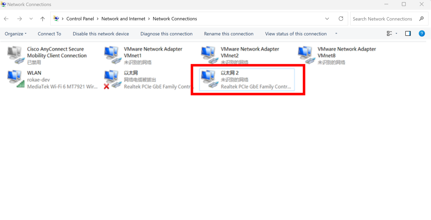
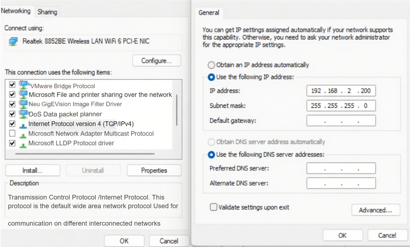
When using a mobile device such as a PC to connect to a robot, it is necessary to ensure that the LAN port address of the mobile device is in the same network segment as the robot. Regarding the modification method of PC (win11) static IP and robot (CR series) connection, you can refer to the following process steps:
| Step | Graphical Representation | Explanation |
|---|---|---|
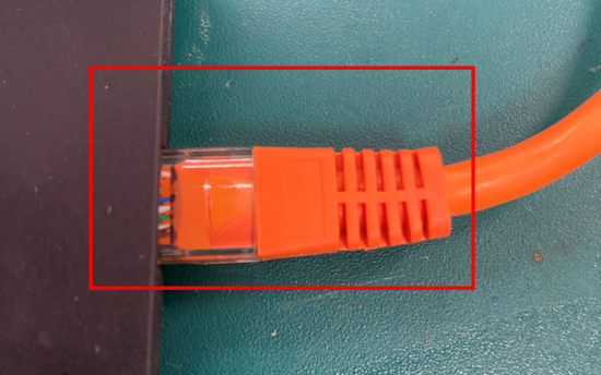
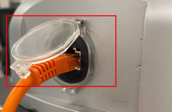
1. Network cable and robot connection. One end of the network cable is connected to the PC network interface, and the other end is connected to the robot network interface. |
|
The default network segment of the network port at the side end of the CR series robot base is "192.168.2.XX". |
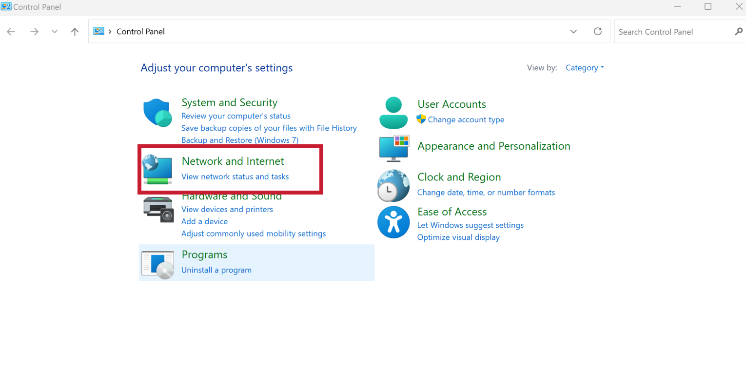
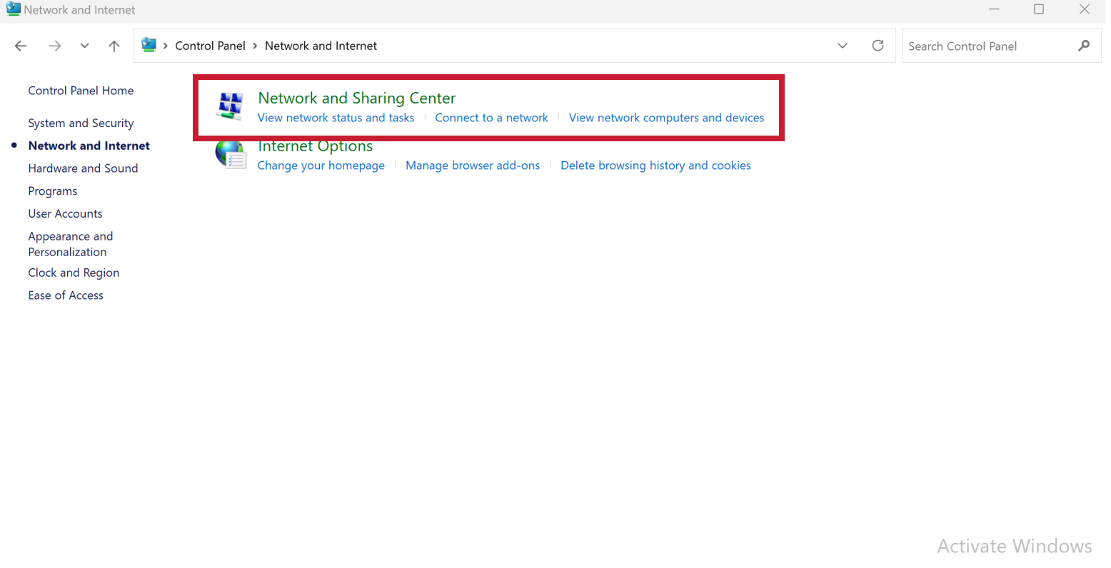
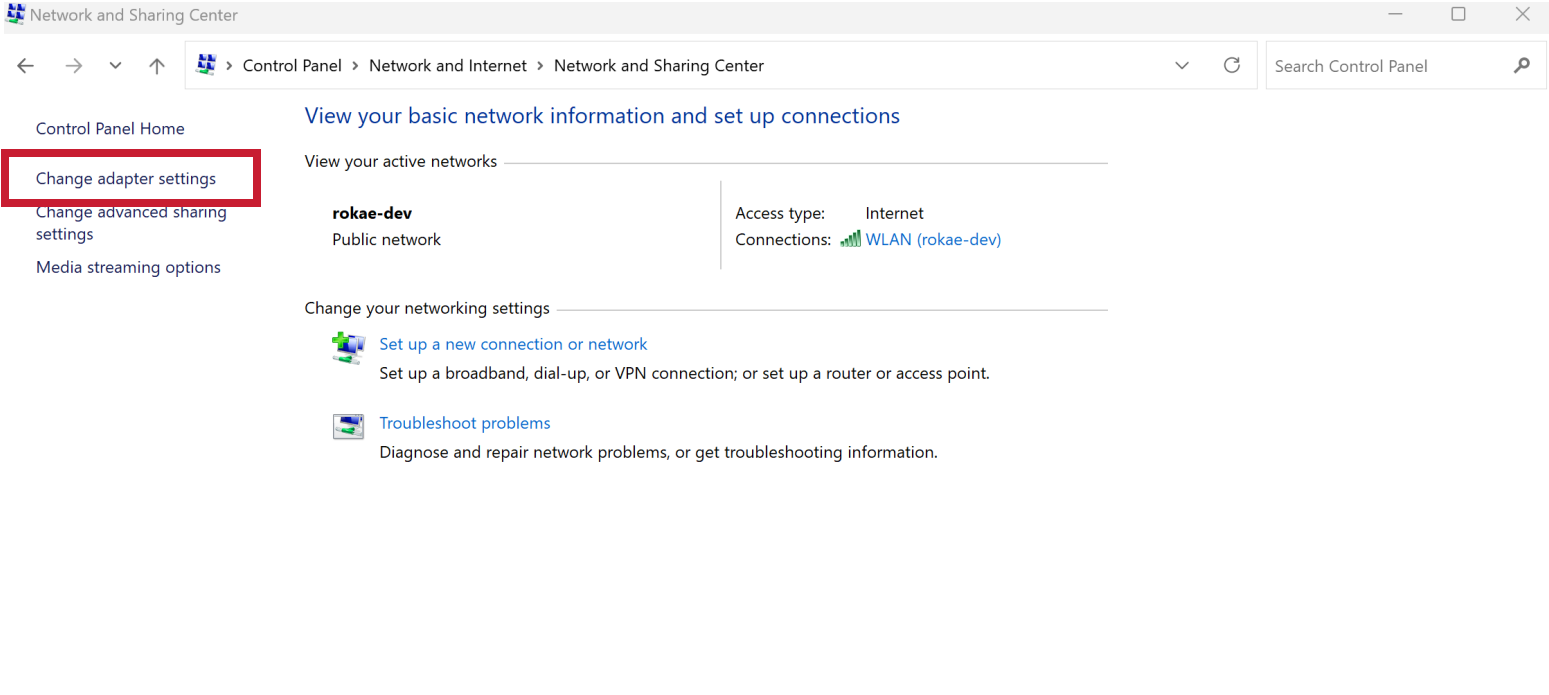
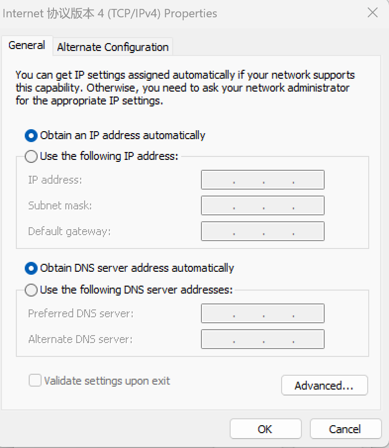
2. Local static IP modification. Enter the PC [Control Panel] → [Network and Internet] → [Network and Sharing Center] → [Change adapter settings] → Right-click to open the corresponding network interface [Properties] → Double-click on [Internet Protocol Version 4 (TCP/IPv4)] → Modify the IP address, subnet mask and default gateway of the terminal device (PC) and click [OK]. |
|
The IP address of the terminal device (PC) can be modified to any IP address that is not occupied in the same network segment as the robot, and its subnet mask and default gateway are consistent with those of the robot. |
3. HMI and robot connection |
|
5.5.2.7.2 Wireless connection of devices such as PC
After the network interface J1 of cobots or the visual network interface of industrial robots is set to DHCP mode, and the robot is connected via the network interface to a router with DHCP, which automatically assigns an IP address to the robot, the robot can then be detected and connected via robot detection.
| Step | Graphical Representation | Explanation |
|---|---|---|
1. Modify the IP property of the robot system to automatic mode. |
|
See Chapter 6 for details; |
2. Connect the robot to a router. |
|
Set the network interface J1 of cobots or the visual network interface of industrial robots to DHCP mode, and connect the robot via the network interface to a router with DHCP, which automatically assigns an IP address to the robot. |
3. Connect the PC to the router network in the same network segment, and set the IP acquisition mode to DHPC. |
|
Enter the [Internet Protocol Version 4 (TCP/IPv4)] page, and refer to the part of Step 2 of the above manual IP modification. |
4. Connect HMI to the robot |
|
5.5.2.7.3 IP address modification
Using the Windows 10 operating system as an example, connect one end of the Ethernet cable to the robot’s J2 interface and the other end to the terminal device (PC); click on the "Start > Control Panel" menu on the terminal device (PC), and select "Network and Sharing Center" (the "Network and Sharing Center" window will pop up); click on "Local Area Connection" in the "Network and Sharing Center" window (the "Local Area Connection Status" interface will appear); click on "Properties" in the "Local Area Connection Status" interface, (the "Local Area Connection Properties" interface will appear); double-click on "Internet Protocol Version 4 (TCP/IPv4)" in the "Local Area Connection Properties" interface, (the "Internet Protocol Version 4 (TCP/IPv4) Properties" interface will appear); and select "Use the following IP address" in the "Internet Protocol Version 4 (TCP/IPv4) Properties" interface, modify the IP address, subnet mask, and default gateway of the terminal device (PC), and confirm the changes. (The IP address of the terminal device (PC) can be modified to any IP address that is not occupied in the same network segment as the robot, and its subnet mask and default gateway are consistent with those of the robot)
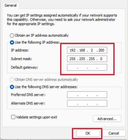
|
When manually modifying the IP address of the robot’s network interfaces, do not set different network interfaces as static IP addresses of the same network segment; do not arbitrarily modify the network mode and IP address (192.168.0.160) of the debugging network interface; do not arbitrarily modify the network mode and IP address (192.168.1.160) of the Teach Pendant xPad’s network adapter card. |
5.5.3 Robot detection and connection
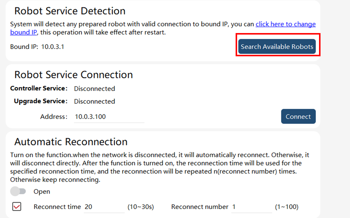
HMI can detect and display all robots available on the same network segment for connection. You can detect and connect robots by following these steps.
| Step | Graphical Representation | Explanation |
|---|---|---|
1. Search for available robots. Click on the network icon |
|
When searching for robots, please make sure the device on which Robot Assist is running and the robots are on the same network and the network is connected. |
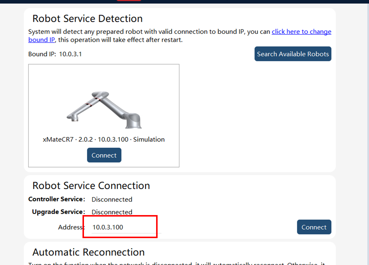
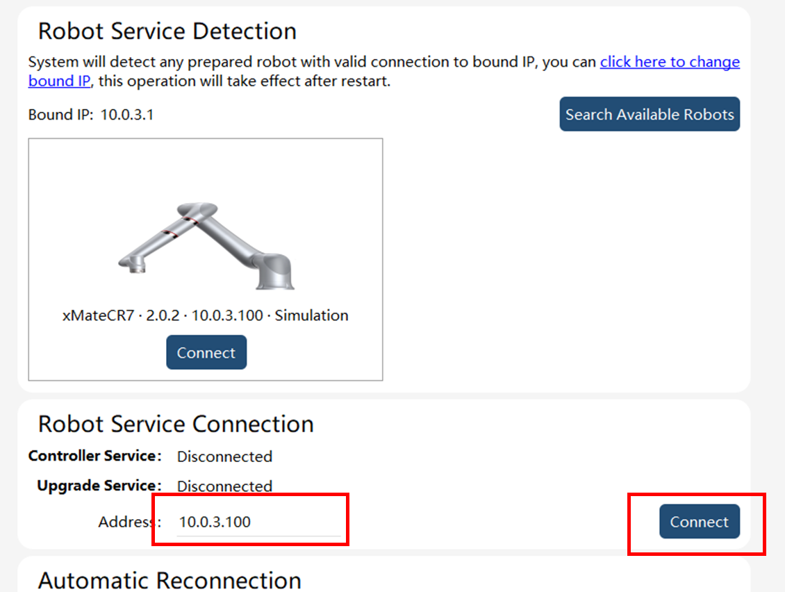
2. Connect the robots. Enter the IP address of the robots and click on [Connect] . |
|
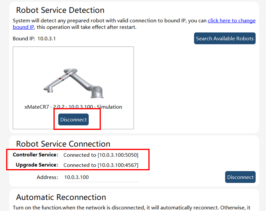
When the robots are connected successfully, [Controller Service] and [Upgrade Service] will display "Connected to XXXX". The bottom status bar icon changes to |
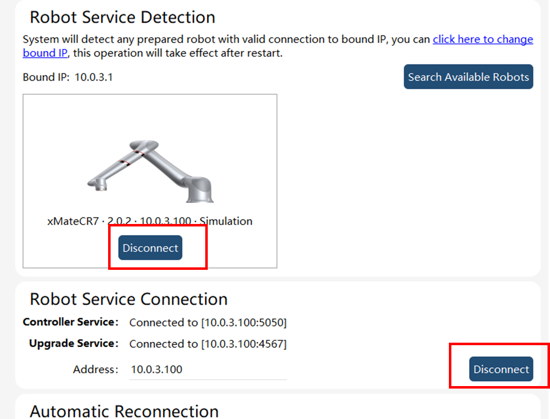
3. Disconnect the robots. Click on the Disconnect button in the Connection interface to disconnect Robot Assist from the controller. |
|
The Robot Assist connection can be restored in the same way it is connected for the first time. |