8.3.1 Overview
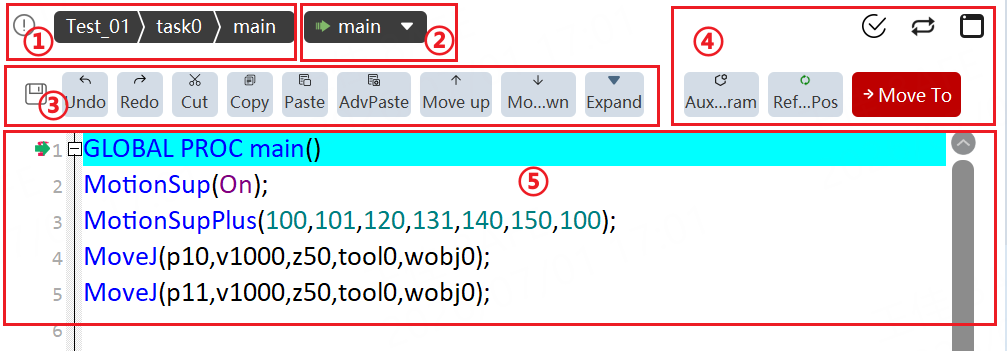
① |
Selection, switching, and editing of project, task, and program files. |
② |
Program debugging quick positioning button, supporting (1) Quick positioning to the main function; (2) Quick positioning to the cursor; (3) Quick positioning to a certain function of the current program module. |
③ |
Save button: Save the current task. If the program is modified during debugging, click this button, and the pointer hot update will be enabled, and the current program modifications will take effect in the controller. Program edit toolbar: Save, Undo, Restore, Cut, Paste, Copy, Reverse paste, Move up one row, Move down one row, Batch comment, Delete current row, Find, View location, Quick edit, Batch modify, and Offset. |
④ |
Auxiliary programming, updating the position information of a point, moving to a certain point, program syntax check, loop mode, and output terminal. |
⑤ |
Program editing area, where RL commands are edited through auxiliary programming and other methods. |
8.3.2 Tool introduction
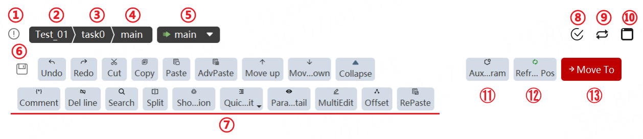
① |
Project synchronization identification. Red identification means that the loading program in the controller is not synchronized with the current program on the HMI. Gray identification means that the loading program in the controller has been synchronized with the current program on the HMI. |
② |
Current project: Click to switch to the project configuration page. |
③ |
Current task: Click to switch between tasks. |
④ |
Current program module: Click to switch between program modules. |
⑤ |
Clicking and dragging the dropdown clamp of the pointer allows you to select the target for the pointer to move to. You can move the program pointer to the Main function (equivalent to program reset), move the program pointer to the line where the cursor is located, or move the program pointer to a specific function. Note: The functions, such as moving the program pointer to the line where the cursor is located or to a specific function, are available only in manual mode when the current user is a teacher/programmer/admin/system. |
⑥ |
Display the save status. Clicking this button will immediately save the program locally and push it to the controller. Green: The program has been edited but is not synchronized to the controller. Gray: The program has been synchronized to the controller. |
⑦ |
Undo the previous operation. |
Redo the previous operation undone. |
|
Cut the selected line of code. Multiple lines can be cut at the same time. |
|
Copy the selected line of code. Multiple lines can be copied at the same time. |
|
Insert the copied or cut content into the line of the cursor. |
|
When pasting the copied code lines, replace the original points with the new points generated. |
|
Move the selected code line up one line. Multiple lines can be moved up at the same time. |
|
Move the selected code line down one line. Multiple lines can be moved down at the same time. |
|
Comment or uncomment the selected code. |
|
Delete the selected line or the line where the cursor is located. |
|
Search for the keyword within the current file. |
|
Search for the keyword globally. |
|
Replace the keyword in the current file. |
|
Replace the keyword globally. |
|
Split screen: See "Split screen function" below for details |
|
View location: See the "View location function" section below for details. |
|
Quick edit - One-click format: Format all programs in the current project (e.g., add indentation, align operators). |
|
Quick edit - One-click expand: Expand all loaded programs in the current RL editor. |
|
Quick edit - One-Click collapse: Collapse all loaded programs in the current RL editor. |
|
Click the point, variable, tool, work object, I/O, or register to jump to the management interface. |
|
Batch modify: Perform batch modifications to speed, turning zone, tool, and work object parameters. |
|
Point offset tool. See "Point offset tool" below for details. |
|
Paste copied lines in reverse order: For example, if lines 1, 2, and 3 are copied, pasting will display them as lines 3, 2, 1. |
|
⑧ |
Check the current program for specific obvious errors, such as duplicate function names and missing key identifiers. It cannot check out all syntax errors. |
⑨ |
Loop mode switching: |
⑩ |
Display Print information and syntax information. |
⑪ |
Auxiliary programming tools. |
⑫ |
Update the pose of the point on the line where the cursor is located to the current pose. Note: Simply position the cursor on the line containing the point. |
⑬ |
"Move to" function, see the "Move to function" section below for details. |


8.3.3 Auxiliary programming
The auxiliary programming interface can assist programmers in quickly building program frameworks, inserting program commands, and changing command attribute configurations. The auxiliary programming interface includes two parts: Insert Command and Attribute Settings.
8.3.3.1 Insert command
Insert Command is responsible for inserting desired commands into program text.
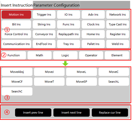
| S/N | Explanation |
|---|---|
① |
Program command group selection area; |
② |
Program common element selection area; |
③ |
Program command/element selection area, for selecting a subdivided command; |
④ |
Command/selection insertion confirmation area, used to insert the default parameters or elements of the selected command into the project text; |
8.3.3.1.1 Example I: Insert MoveL command
| Step | Graphical Representation | Explanation |
|---|---|---|
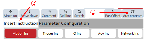
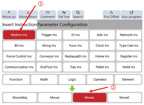
1. Click the "Auxiliary Programming" -> "Insert Instruction" button to open the Insert Instruction interface; |
|
To open the Insert Instruction interface. |
2. Select "MoveL" from "Motion Commands"; |
|
After selecting "Motion Commands", other commands will be hidden. Then, select the "MoveL" command. |
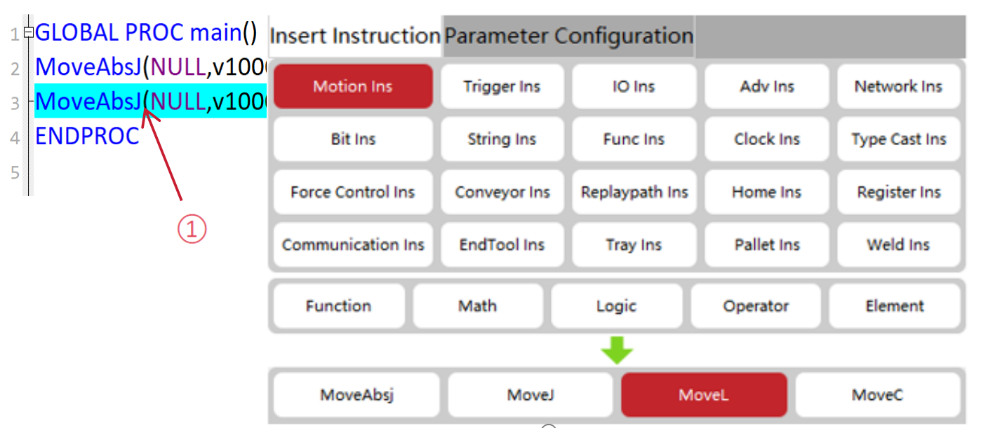
3. Select the previous line of the desired insert line using the cursor; |
|
To select the desired insert line. |
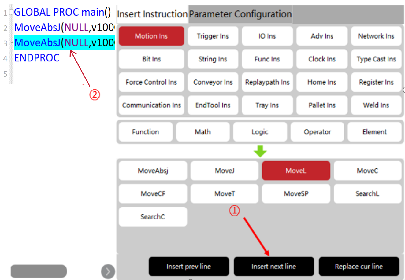
4. Click the "Insert Next Row" button; |
|
To insert the command into the line below the selected line in "3". |
8.3.3.1.2 Example I: Insert a function
| Step | Graphical Representation | Explanation |
|---|---|---|
1. Click the "Auxiliary Programming" -> "Insert Instruction" button to open the Insert Instruction interface. |
|
To open the Insert Instruction interface. |
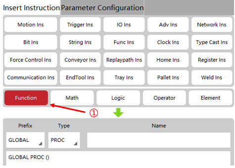
2. Select the "Function". |
|
|
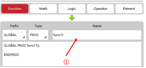
3. In the input box below "Name, " fill in the desired function name. |
|
|
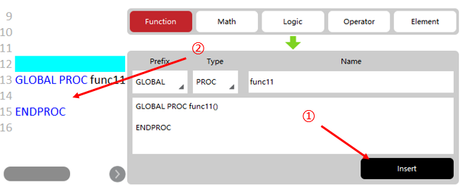
4. Click the "Insert" button. |
|
After clicking the "Insert" button, the text for the corresponding function is created at the end of the text. |
8.3.3.1.3 Example III: Insert an element
| Step | Graphical Representation | Explanation |
|---|---|---|
1. Click the "Auxiliary Programming" -> "Insert Instruction" button to open the Insert Instruction interface; |
|
To open the Insert Instruction interface |
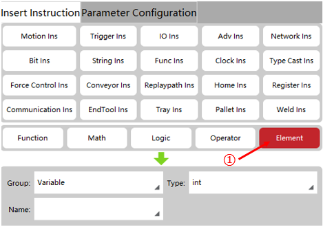
2. Select the "Element"; |
|
|
3. Select the variable and other information you want to insert in the "Element" interface; |
|
|
4. Move the cursor to the desired text position; |
|
|
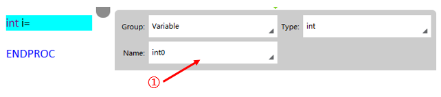
5. Click the "Insert" button; |
|
After clicking the "Insert" button, text will be generated at the corresponding position of the cursor |

8.3.3.1.4 Example IV: Insert math/logic/operator
| Step | Graphical Representation | Explanation |
|---|---|---|
1. Click the "Auxiliary Programming" -> "Insert Instruction" button to open the Insert Instruction interface; |
|
To open the Insert Instruction interface |
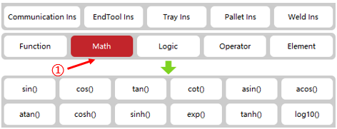
2. Select the "Math"; |
|
|
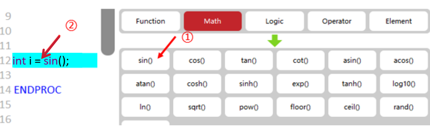
3. Move the cursor to the desired text position; |
|
|
4. Click the "sin()" button; |
|
After clicking the corresponding button, the text sin () will be generated at the corresponding position of the cursor; |

8.3.3.2 Attribute settings
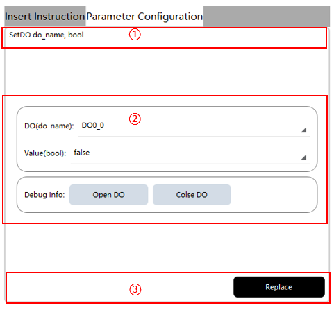
Attribute Settings is responsible for updating the command parameter information for the selected line.
| S/N | Explanation |
|---|---|
① |
Attribute definition area, which describes the parameter name of the current command |
② |
Attribute selection area, for modifying the parameters of the selected command |
③ |
Attribute confirmation area. Click the "Replace" button to replace the command parameters in the current line in the program text |
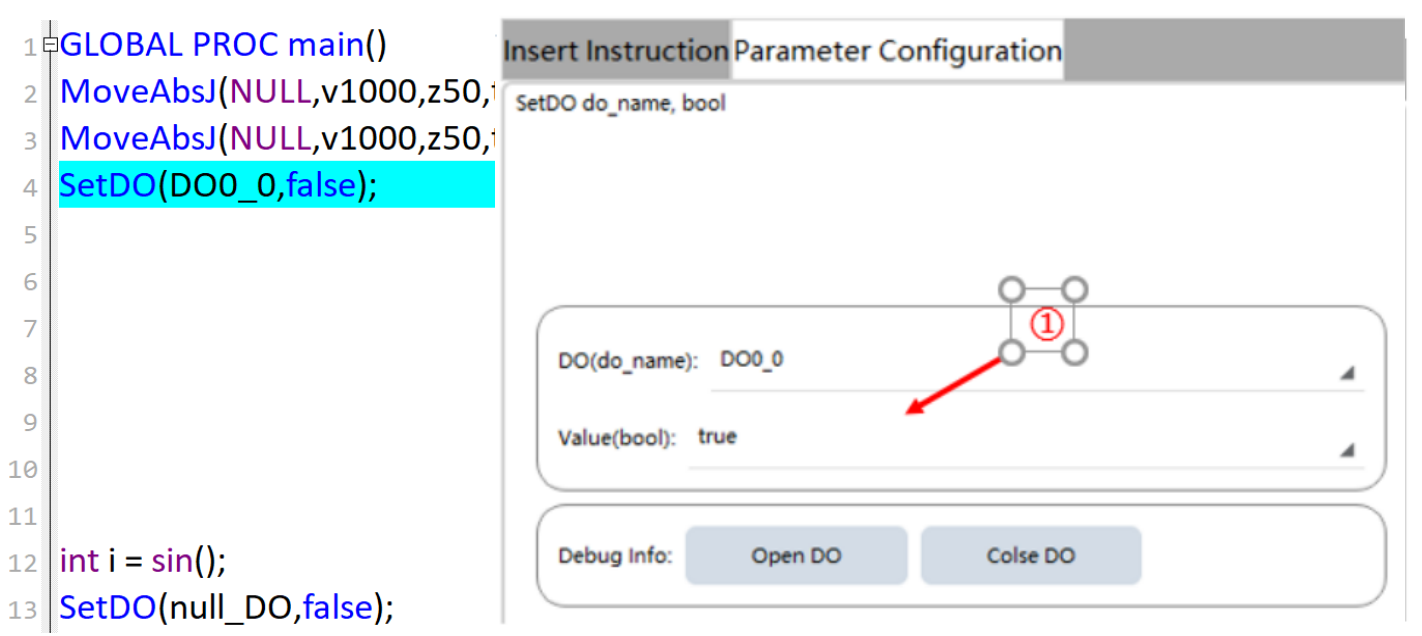
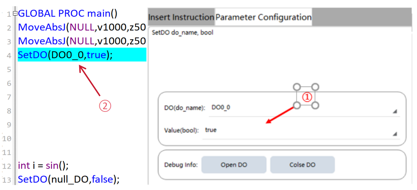
8.3.3.2.1 Example I: Configure the SetDO command attributes
| Step | Graphical Representation | Explanation |
|---|---|---|
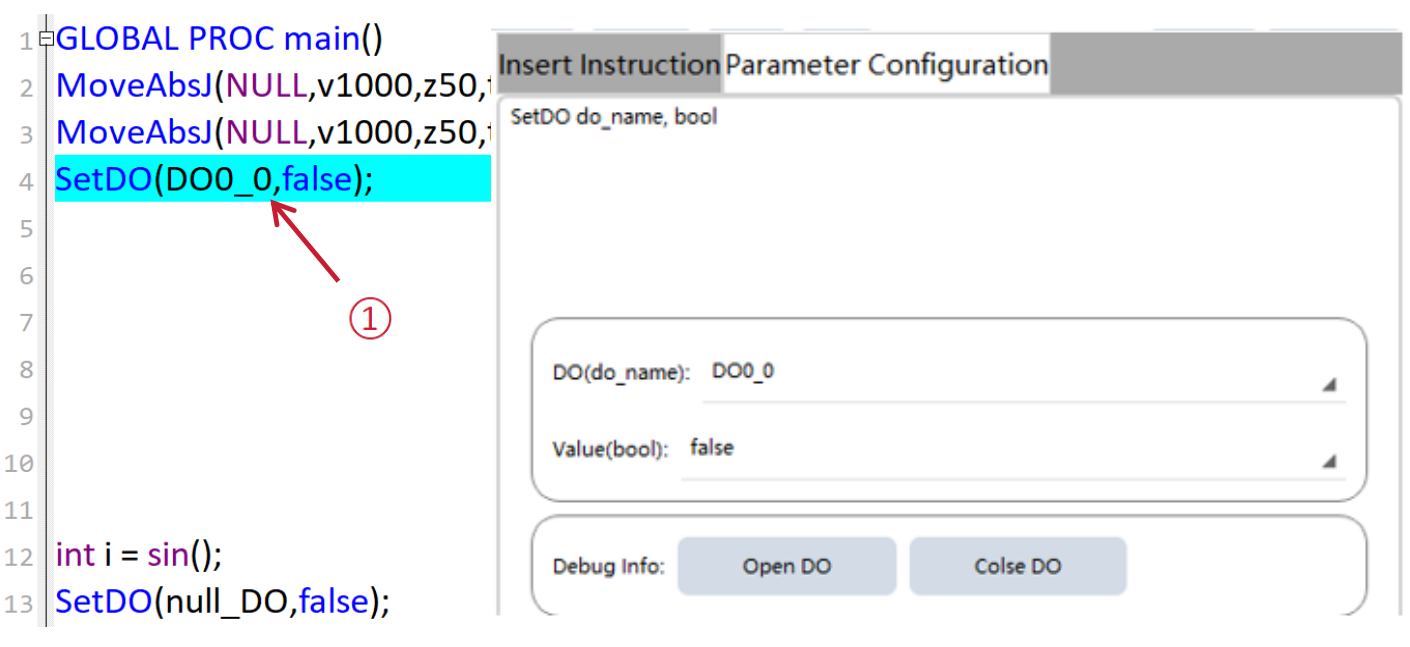
1. Select the desired line containing the command that needs to be modified in the text; |
|
After opening the Attribute Settings interface, the details of the command will be expanded in the interface |
2. Select the desired parameters in the "Attribute Settings" interface; |
|
|
3. Click the "Replace" button |
|
After clicking the "Replace" button, the parameters of the command in the selected line are updated to the set parameters |
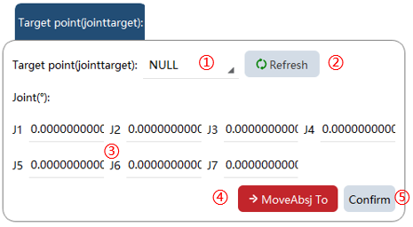
8.3.3.2.2 Example II: Configure the MoveAbsJ command attributes
| S/N | Graphical Representation | Explanation |
|---|---|---|
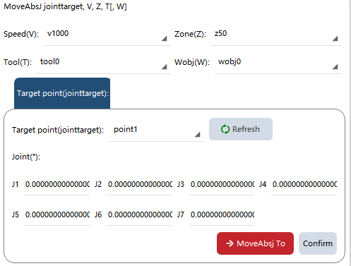
1. Motion parameter settings; |
|
Set the speed, turn zone, tool, and work object parameters of the MoveAbsJ command. |
2. Point setting; |
|
1. Select the point; 2. Update the pose information of the selected point to the robot’s current pose; 3. Point information can be manually modified; 4. Manually Jog the robot to the selected point; 5. Click the "OK" button to update the data modified in 3 to the point data; |
8.3.3.2.3 Example III: Configure the MoveL command attributes
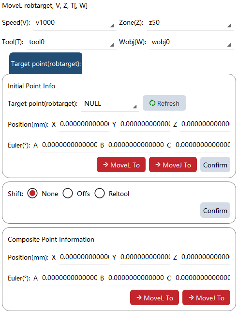
| S/N | Graphical Representation | Explanation |
|---|---|---|
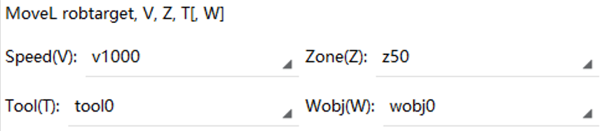
1. Motion parameter settings; |
|
Set the speed, turn zone, tool, and work object parameters of the MoveL command; |
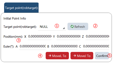
2. Point setting; |
|
1. Select the point; 2. Update the pose information of the selected point to the robot’s current pose; 3. Point information can be manually modified; 4. Manually Jog the robot to the selected point; 5. Click the "OK" button to update the data modified in 3 to the point data; |
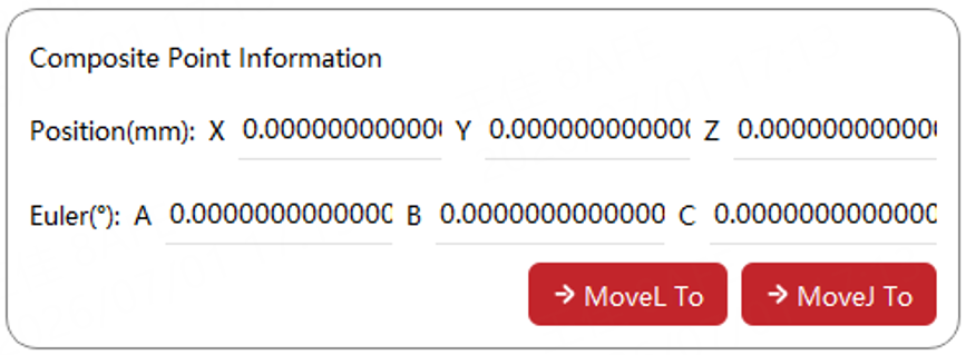
3. Offset setting |
|
|
4. Offset point debugging interface. |
|
This interface is non-editable and is intended for use after applying an offset through Jog settings. |

8.3.3.3 Quick insert
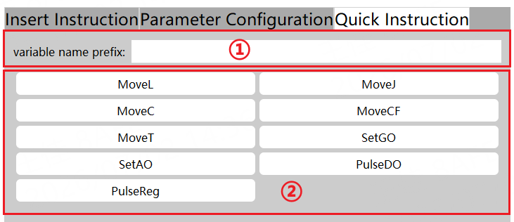
Quick insert is available for inserting desired commands into the program text.
| S/N | Explanation |
|---|---|
① |
Specify the prefix for the variable name of the quick insert command. If not specified, the default is used. |
② |
Quick insert command selection area. |
8.3.3.3.1 Example 1, insert the MoveL command
| Step | Graphical Representation | Explanation |
|---|---|---|
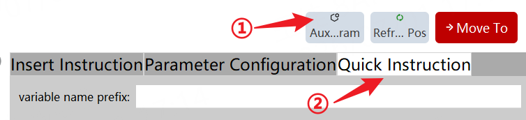
1. Click the "Auxiliary programming" -> "Quick insert" button to open the quick insert interface. |
|
Open the quick insert interface. |
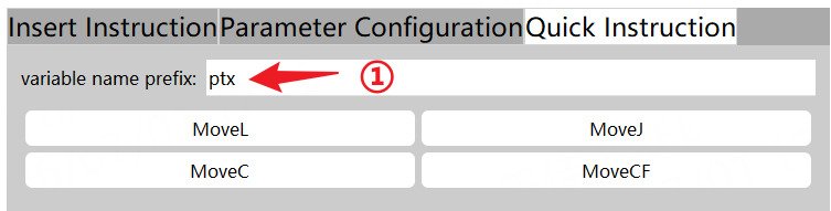
2. Input the prefix for the variable name. |
|
If the prefix for the variable name is null, a new variable will be created using the default naming rule. |
3. Click the "MoveL". |
|
Insert the MoveL command into the next row below the cursor, and take the specified prefix as the point name. |

8.3.4 Point offset tool
8.3.4.1 Overview
This tool allows for global offset modification of taught points within a user-selected range of motion commands in an RL program. The current controller version supports three offset methods: Program offset, Angle offset, and Mirror offset.
8.3.4.2 Program offset parameters introduction
This tool allows for the global offset of taught points within a user-defined range of motion commands in the RL program.
When the work object is required to be translated only, the parallel offset is used, and only the xyz values are adjusted. When you want to adjust both the position and attitude of the work object, after the "Orientation Variable" is turned on, the orientation values ABC will also be adjusted.
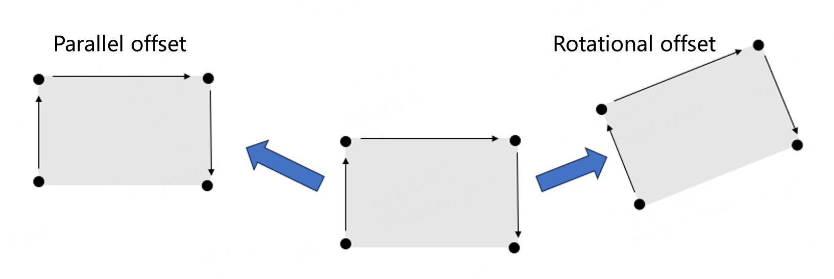
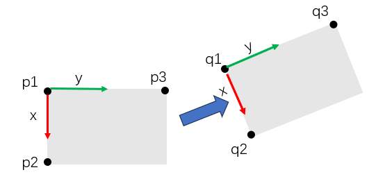
Principle: Calculate the relationship between the original frame and the offset frame through 6 points including p1, p2, p3, q1, q2, and q3. When "Pose Variable" is not turned on, only p1 and q1 need to be set.
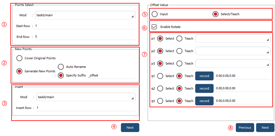
① |
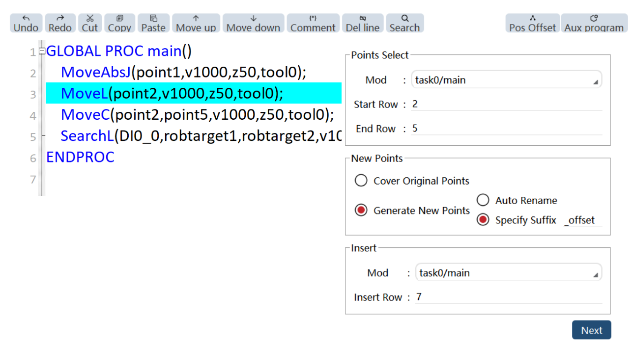
Point Selection: Select the position of the point that needs to be offset, and specify task and mod, start line, and end line. Then, this tool will search for the points involved in all commands from the start line to the end line. Attention: Commands commented out with "//" are not searched. |
② |
New point generation method: You can choose between "Overwrite Original Point" or "Generate New Point". If "Generate New Point" is selected, you can choose the naming method for the new point: "Automatic Renaming" or "Original Point Name+Specified Suffix". |
③ |
Insertion position: Specify the position where the newly generated command will be inserted. By selecting either task or mod, the generated command text will be created starting from the designated insert line. |
④ |
Click the "Next" button to go to the Offset setting page. |
⑤ |
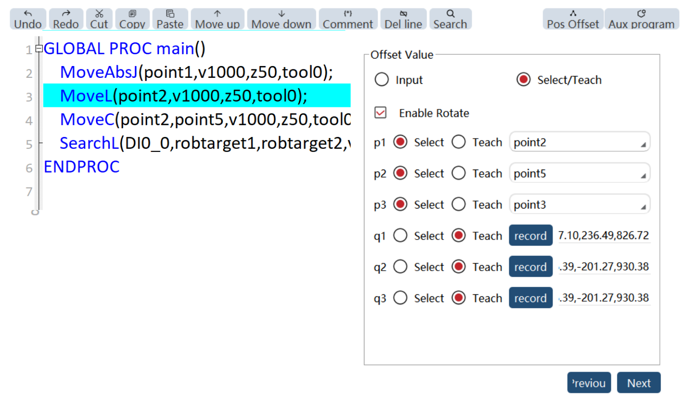
Offset matrix generation method: "Input" or "Select/Teach" can be selected, and the "Pose Variable" is supported only in the latter. |
⑥ |
Choose whether the pose is variable or not. If not, only translation is considered. |
⑦ |
Under the "Select/Teach" condition, 2 points or 6 points used to calculate the pose need to be specified. For each point, you can select the "Select", and then select the existing points in the corresponding pull-down list. You can also select "Teach" and click the "Record" button to record the current position of the robot. |
⑧ |
Click the "Back" button to enter the Point Selection page. Click the "Next" button to start calculating the offset points. |
Use restrictions:
1. It is recommended to keep the number of offset points per time within 1000, otherwise, interface freezing or loss of points may occur.
2. When the system calculates an offset point, it will automatically check whether the point is reasonable, and if not, an error message will be displayed, and the generation of commands will fail. But the points before the unreasonable points will still be generated.
Cause of point unreasonableness: ① Parameter error ② Singular position ③ Point unreachable ④ Other errors.
3. If there is no point between the start line and the end line of the specified mod, an error message, "No point to be offset found", will be reported.
4. The robot needs to be connected when this tool is used, otherwise, an error message of "robot communication error" will be reported.
5. The angle between the vectors formed by any two points of p1, p2, and p3 shall be greater than 1°, otherwise, it will be judged that the three points are collinear and an error message of "reference point error" will be reported; The same applies to q1, q2, and q3.
6. The point name in the command needs to be consistent with that in the point list (case-insensitive), otherwise, an error message of "point xxx not found" will be reported.
7. When the tool page is open, and when you perform operations such as adding or removing tasks, adding or removing points, editing RL, and switching between projects on the "Task List", "Point List", and RL editing pages, this tool will not automatically refresh. It is necessary to close and reopen the tool page manually for refreshing this tool.
8.3.4.3 Angle offset parameters introduction
This function provides angular offset capability for Cartesian points. It allows for rotational offset of taught points within a user-defined range of motion commands in the RL program by specified angles.
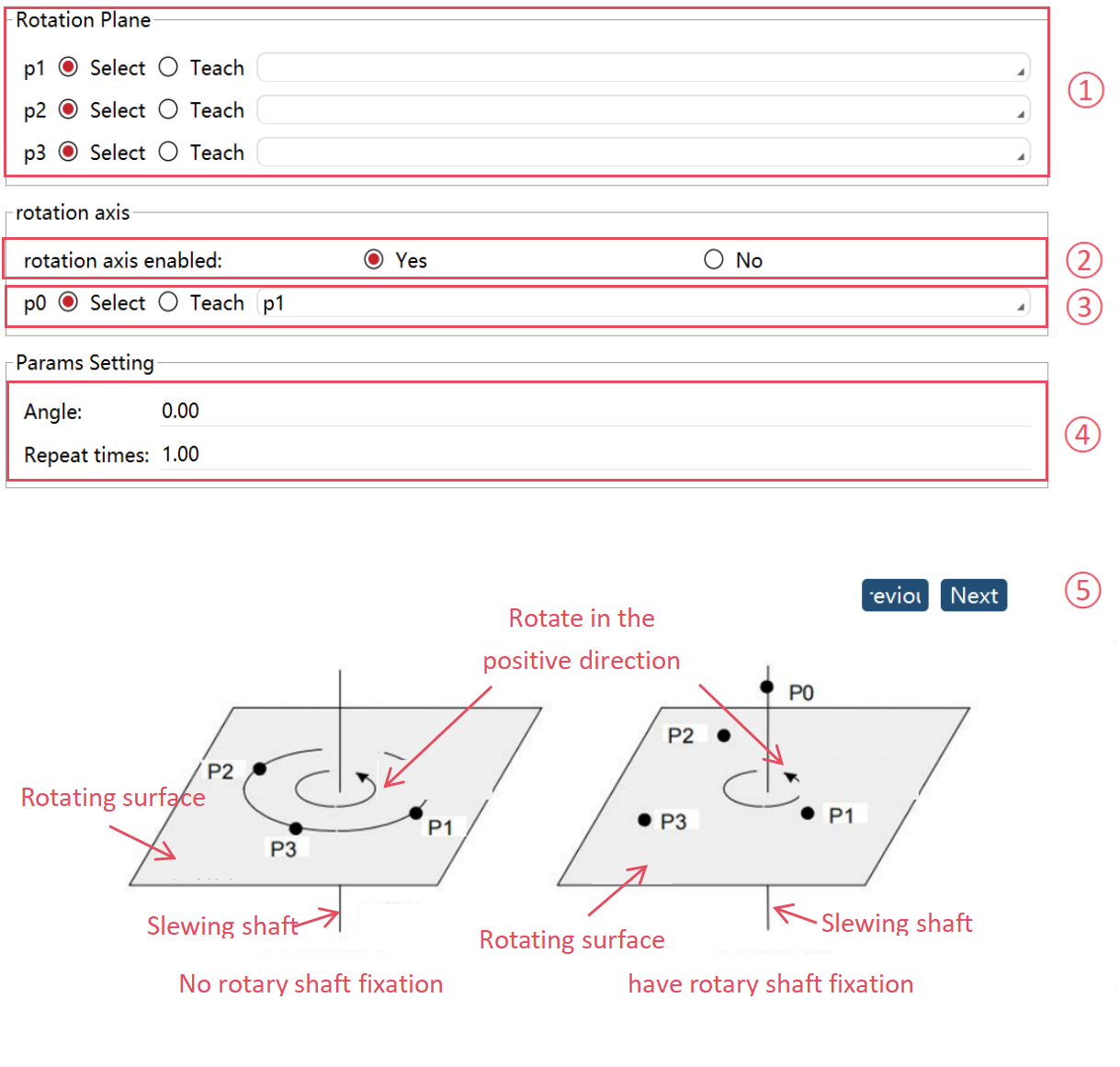
The point selection for Angle offset is identical to Program offset. After the effective range is selected, perform the following operations to complete the angular offset.
① |
Define the rotation plane: The user needs to specify three points (p1,P2, P3) to determine the reference rotation plane for the Angle offset function. These three points can be selected from the point list or confirmed through teaching. |
② |
Disable rotation axis: |
③ |
Enable rotation axis: |
④ |
Set offset angle and repeat count: This function will rotate the points multiple times, generating a new set of motion commands for each repetition. |
Note:
-
This function does not support angular offsets for joint-space points
-
After performing angular offsets, the orientation of robot points in the new RL program may differ from the original program. Always verify through manual slow-speed single-step execution and individual point confirmation before initiating continuous operation
8.3.4.4 Mirror offset parameters introduction
This function provides mirror offset functionality for Cartesian points. Users can select the points to be offset and apply mirror offsets according to specified rules.
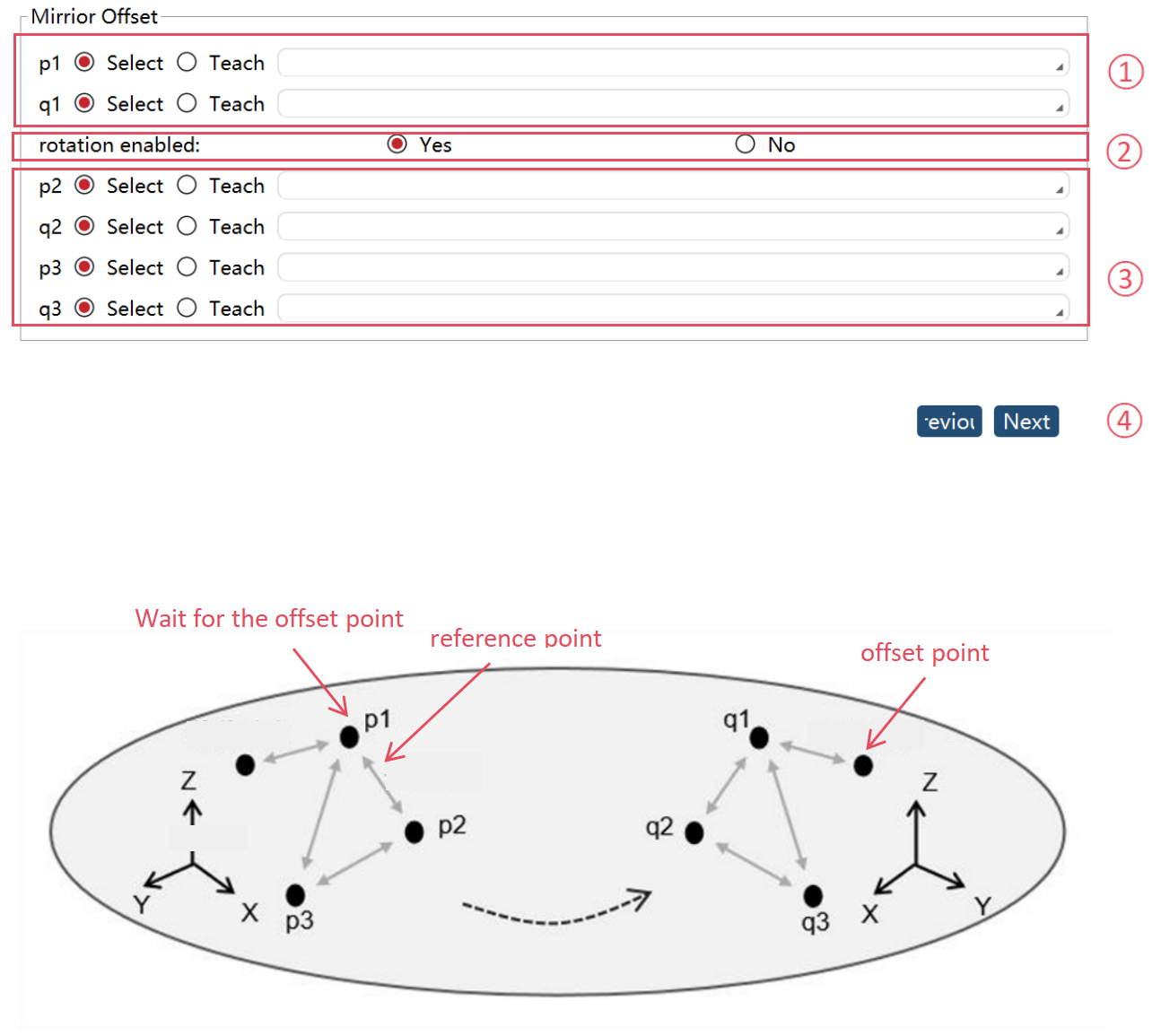
The point selection for Mirror offset is identical to Program offset. After the effective range is selected, perform the following operations to complete the mirror offset.
① |
Select mirror points: Choose reference points p1 and q1 as the mirror basis. These points can be selected from the point list or taught manually. |
② |
Rotation disabled: Set [Use rotation] to "No", the system will calculate the mirror plane based on the positions of p1 and q1. The position of the point to be offset will be mirrored across this plane, while its orientation remains unchanged before and after the offset. |
③ |
Rotation enabled: Set [Use rotation] to "Yes". Additional reference points p2, q2, p3, and q3 must be specified. The triangle formed by (p1,p2, p3) must be symmetrical to the triangle formed by (q1, q2, q3) across the intended mirror plane. In this mode, both the position and orientation of the points to be offset will be mirrored across this plane, resulting in symmetrical orientations before and after the offset. |
8.3.4.5 Operation examples
| Step | Graphical Representation | Explanation |
|---|---|---|
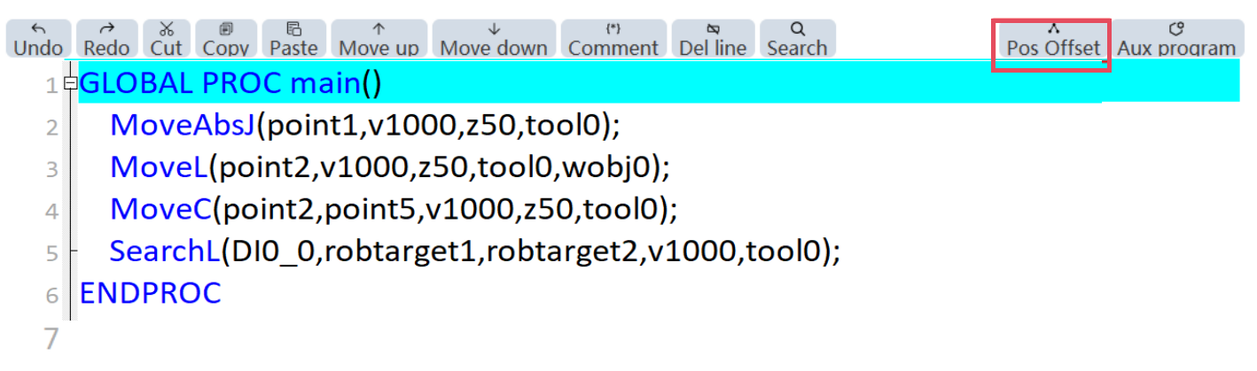
1. Click the "Point Offset" button to open the tool; |
|
It can only be used in manual mode with the permission level of "Programmer" and above; |
2. Select the point to be offset, set the parameters, and click the "Next" button; |
|
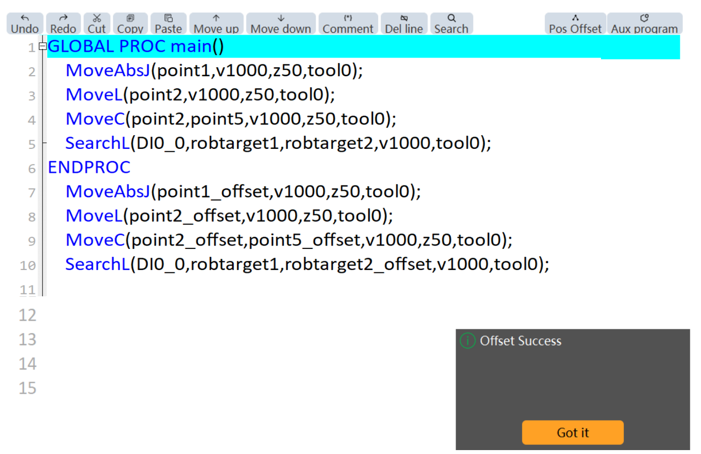
Here, select the points of lines 2 to 5 in the "main" of the "task0" task; The point generation method is "generate a new point", with the name suffix of the new point needing to be specified; The insertion position selects the 7th line of the "mod" file; |
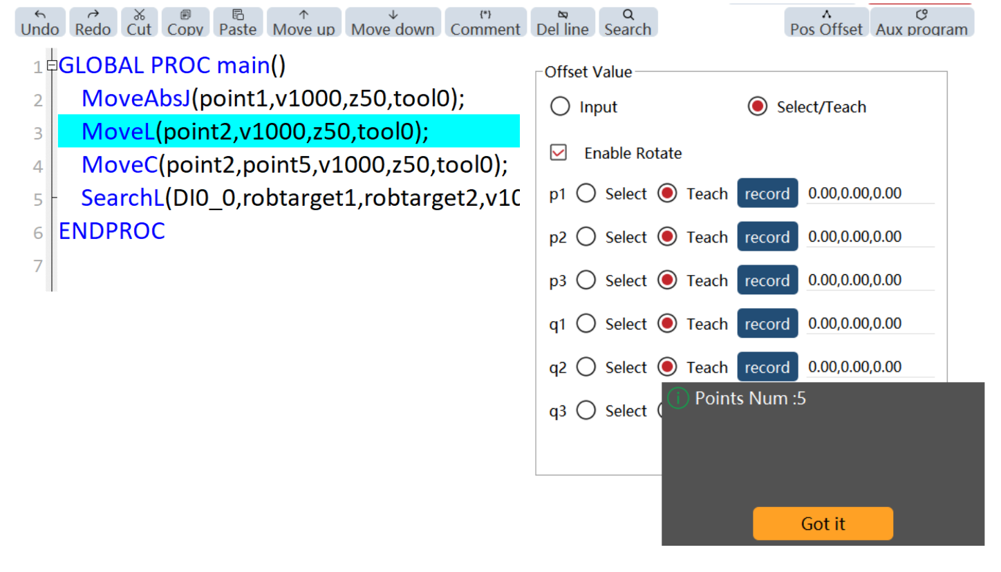
3. Prompt "number of points to be offset"; |
|
The points to be offset here are point1 in line 2, point2 in line 3, point2 in line 4, and robtarget2 in line 5. Note: 1. The "point2" is calculated twice, but it actually will be offset only once, so only one offset point will be generated. |
4. Set the offset calculation method and reference point, and click the "Next" button; |
|
As the progress bar pops up during the execution of the offset, please wait patiently;
|
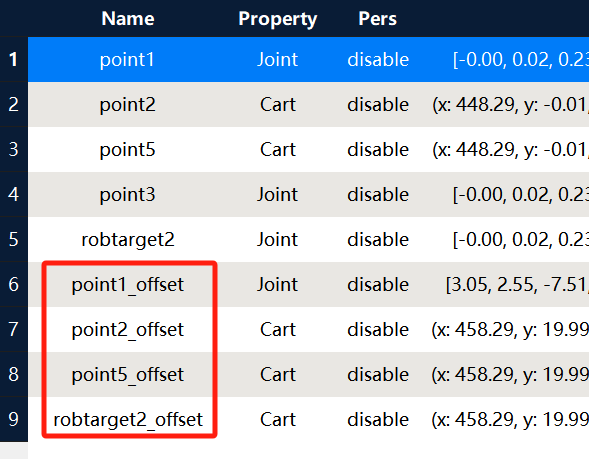
5. Prompt "offset successful". The contents of the 7th to 10th are newly generated commands; |
|
You can see the generated point information in the point list;
|

8.3.5 Move to function
"Move to" Function: This function enables the robot to move to the selected point by executing a series of operations;
8.3.5.1 Operation examples
| Step | Graphical Representation | Explanation |
|---|---|---|
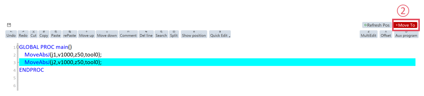
1. In the RL editor interface, select the corresponding motion command; |
|
It can only be used in manual mode with the permission level of "Programmer" and above; |
2. Click the "Move to" button in the top-right corner; |
|
|
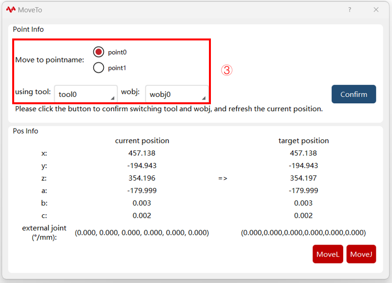
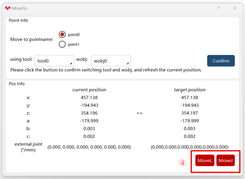
3. In the "Move to" pop-up window, select the corresponding tool, work object, and point; |
|
Single-point motion command: No need to select a point; Multi-point motion command: Confirm the selected points; Choose the tool and work object for the move to; |
4. In the "Move to" pop-up window, select the target point and execute the "Move to" function. |
|
Select "MoveJ, " "MoveL, " or "MoveAbsJ" (displayed only for joint angle points) in the bottom-right corner, and long press to trigger the "Move to" function. |

8.3.6 View location function
8.3.6.1 Overview
"View location" function: This function is primarily designed for users to identify the current stop position of the robot and determine which line of the RL program it corresponds to.
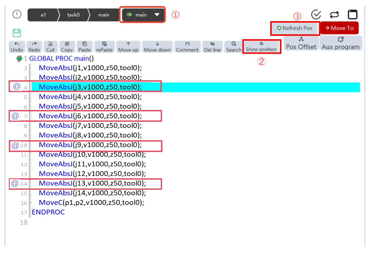
Triggering the view location function can be done in the following ways:
-
Clicking the "PPToMain" button;
-
Clicking the "View Location" button;
-
Clicking the "Update Position" button;
When the "view location" function is triggered, a image::en/image226.png[width=700,align=center]symbol will be displayed on one or more lines in the RL program interface, indicating that the robot’s current position matches the point position used on those lines.

8.3.7 Split screen function
8.3.7.1 Overview
The function is primarily designed to facilitate quick access to I/O information, register information, and other function interfaces while users edit RL programs;
8.3.7.2 Steps
| Step | Graphical Representation | Explanation |
|---|---|---|
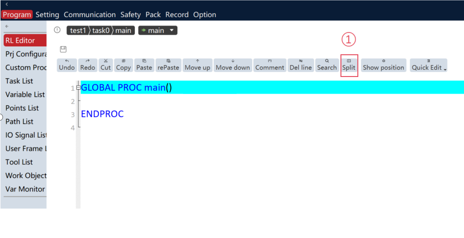
1. Click the "Split screen" button in the top toolbar; |
|
It can only be used in manual mode with the permission level of "Programmer" and above; |
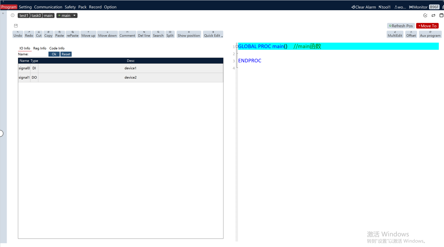
2. Display the left split-screen interface; |
|
During split-screen mode, the right operation panel and left menu panel automatically close; When exiting split-screen, the two panels automatically expand; |
3. Switch split-screen information display |
|
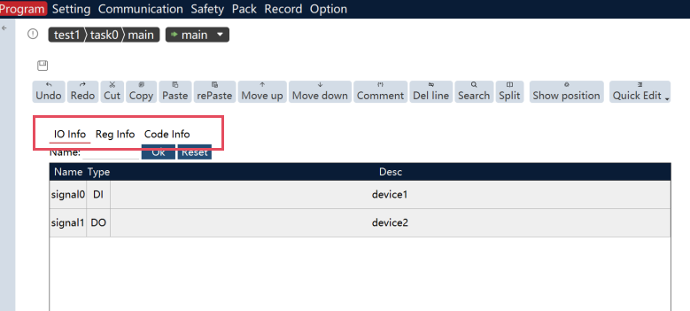
Click the tab bar on the split-screen panel to switch between I/O information, Register information, and RL information views; The I/O list and Register list support name search functionality; |
8.3.8 Tool/work object pointer following function
When the robot is in Manual mode, the tool/work object group in the upper-right corner of the teach pendant will automatically switch to match the tool/work object assigned to the currently selected RL program line. Note: This function is not supported for custom tools/work objects defined in the RL program.
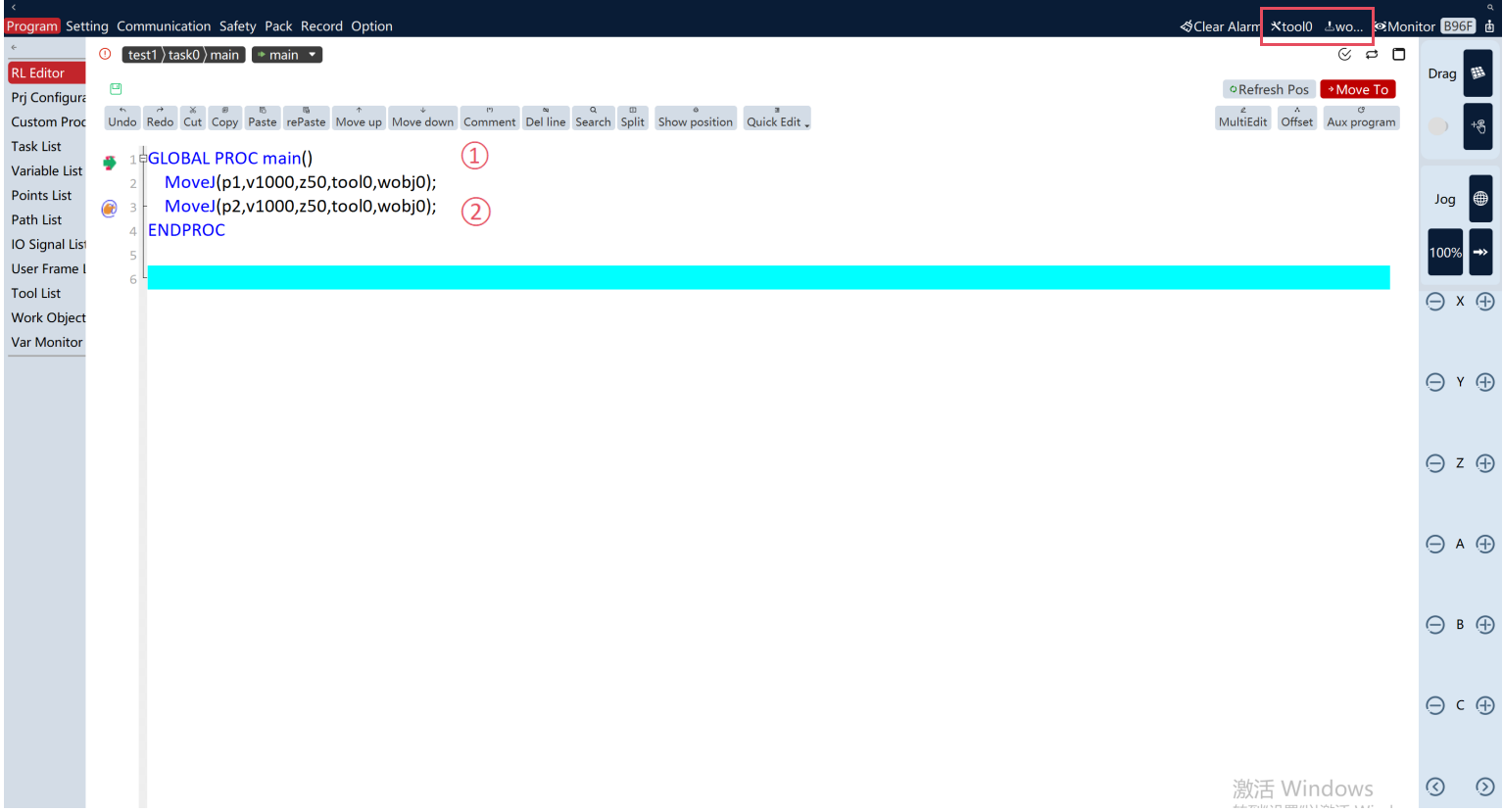
① When Line 2 is selected, the tool/work object in the upper-right corner automatically updates to tool0, wobj0
② When Line 3 is selected, the tool/work object in the upper-right corner automatically updates to g_tool_0, g_wobj_0