8.12.1 Overview
A tool is a device that is installed on the flange of a robot to complete a specific processing procedure. Common tools include pneumatic/electric grippers, welding guns, and sprinklers. No tool is attached to the robot when it is delivered from the factory, and you need to purchase or design appropriate tools according to the actual situation and complete the installation and settings in order to make the robot work.
Any tool shall be calibrated to get the TCP data before it is used.
In the xCore controller system, the data type corresponding to tools is "tool". For detailed explanations of the "tool", please refer to the section "RL Commands-Variables".
8.12.2 Basic concept
Tool attributes include: center point and orientation, which represent the geometric parameters of the tool; and weight, center of mass and rotational inertia, which represent the dynamic parameters of the tool.
|
tool0 is a tool variable pre-defined by the system. Its tool frame coincides with the flange frame and both share the same dynamic parameter of 0. The tool0 variable is not allowed to be modified. |
8.12.2.1 Tool center point
Tool Center Point (TCP) is a specific point on the tool that is normally used by the robot to carry out processing work, such as the wire tip of a welding gun and a tip of a pneumatic gripper. The robot can rotate around the TCP and change its orientation while keeping the position of the TCP unchanged.

Different tools may have different TCP, and determining an appropriate TCP according to actual conditions can significantly increase programming efficiency.
|
Unless otherwise specified, all references to "robot position, velocity, acceleration" in the Manual refer to the position, velocity, and acceleration of TCP relative to the work object frame. |
8.12.2.2 Tool frame
The calibration of tool frame refers to the process of determining the pose of the tool frame relative to the flange frame.
If the pose information of the tool relative to the flange is known, you can select "manual input" on the teach pendant and input it directly without performing the calibration process.
If the pose information of the tool relative to the flange is unknown, xCore provides three methods for tool frame calibration:
-
Four-point method, used to calibrate the center point of the tool frame.
-
Three-point method, used to calibrate the orientation of the tool frame.
-
Six-point method, used to calibrate the center point and orientation of the tool frame at the same time, which is equivalent to the integration of the four-point method and the three-point method.
Additionally, xCore provides the "TCP correction function" to further improve the position accuracy after tool frame calibration.
8.12.2.3 Load parameters
The xCore system utilizes load-type variables to store the load parameters of tools. Attention: When external tools are used, the load parameters in the tool variables store the load of the handheld work object.
There are two ways to define a tool’s load parameters:
If the user knows the tool load data, the user can select the manual input method on the tool frame calibration interface and input the corresponding data directly;
If the tool load data are unknown, they can be obtained using the load identification function of the xCore system.
Either by direct input or load identification, the load curve of the model will be used to evaluate the rationality of the final load parameters, thereby recommending the appropriate tool to the users:
-
Load torque/inertia exceeds 1 to 1.5 times the limit: The load information setting is abnormal. The set load information will cause the inertia or torque at the end-effector to exceed the limit by 1 to 1.5 times.
-
Load torque/inertia exceeds 1.5 times the limit or above: The set load information will cause the inertia or torque at the end-effector to exceed the limit by at least 1.5 times.
8.12.2.4 Load identification
The load identification function can conveniently calculate the dynamic parameters of the tool.
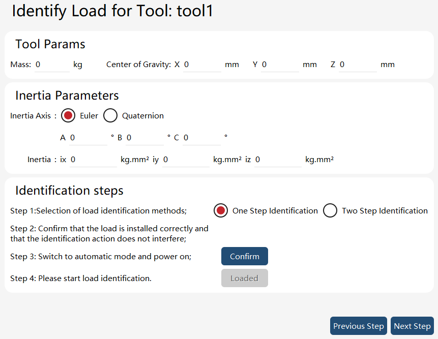
Two methods are supported for load identification: one-step identification and two-step identification. Industrial robots only support two-step identification, and the precision of two-step identification is usually superior to that of one-step identification.
"Two-step identification" operation procedure:
1. Select the two-step identification method for load identification;
2. With no load attached, switch the robot to manual mode and power it on; then press and hold “Move To” to reach the identification position;
3. Switch to automatic mode, power on the robot, and click “Confirm”;
4. Click “No-load Identification” to run the no-load identification program in the no-load state and wait until the program completes;
5. After correctly installing the load, switch the robot back to manual mode, and press and hold “Move To” to reach the loaded identification position;
6. Switch to automatic mode, power on the robot, and click “Confirm”;
7. With the load attached, click “Loaded Identification” to run the loaded identification program and wait until the program completes;
8. When the identification is completed, the identification result window pops up. Click "Save" to save.
For collaborative robots, both the "one-step identification" and "two-step identification" are available, among which the latter has the same procedure as above, and the former is described as follows:
1. Select the one-step identification method for load identification;
2. Install the load and ensure that it is properly mounted and that there is no interference during the identification process;
3. Switch the robot to manual mode and power it on; then press and hold “Move To” to reach the identification position;
4. Switch to automatic mode, power on the robot, and click “Confirm”;
5. Click the "Loaded button" to run the identification program and wait until the program completes;
6. Confirm the identification results and save them.
|
Please make sure to accurately define the dynamic parameters of the new tool. Otherwise, failure to do so will affect the motion of the robot and even damage the robot due to excessive load on some serious occasions. Before identification, switch on and preheat the robot in advance for more than half an hour to improve the identification precision. Load inertia calculation is based on the flange frame. Load identification is only supported when the robot is installed upright. |
|
The following circumstances during identification will cause the identification to stop and cause any identification data received to be lost. In this case, the user has to re-start the identification:
|
|
The identification program needs to be executed in the automatic mode, so all prevention measures shall be effective. As the external control signal may start the robot at any time, you need to switch to automatic mode for identification program execution only after the installation is complete and all personnel have retreated to a safe area. |
8.12.2.5 TCP correction
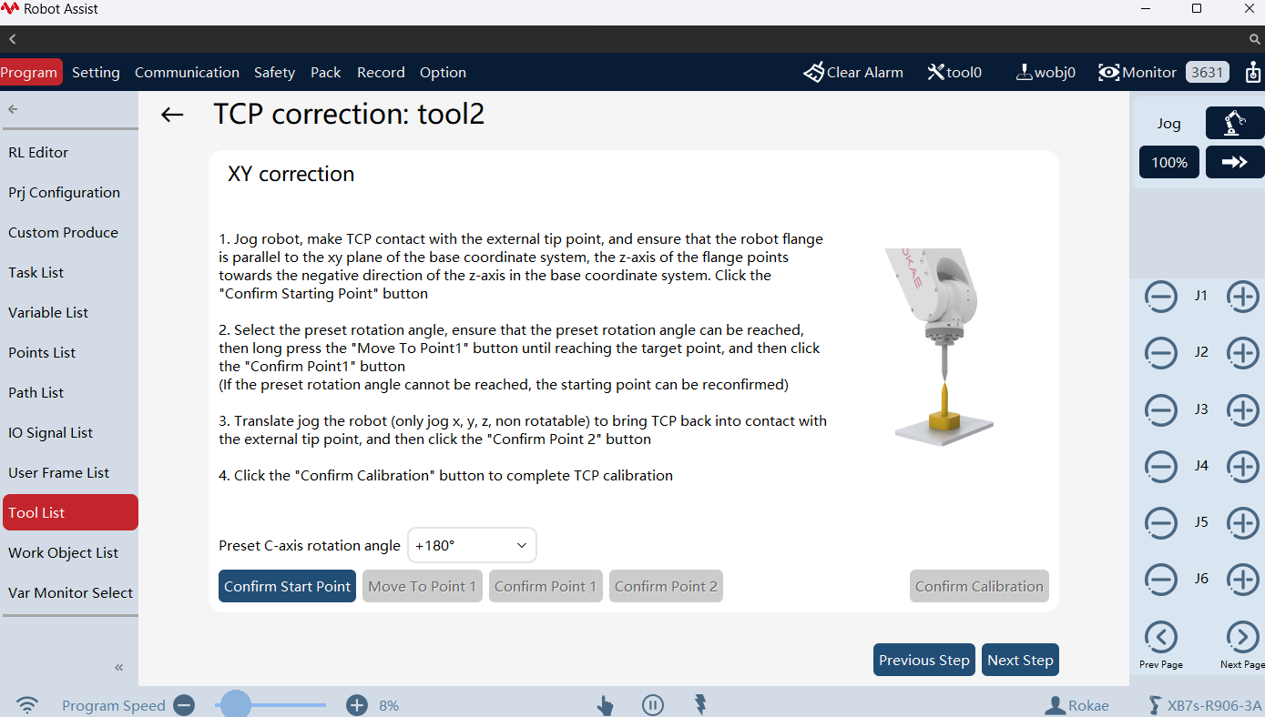
xCore provides the TCP correction function to correct the Tool Center Point (TCP) of the tool frame. For handheld tools that have undergone pose calibration, use the TCP correction function to improve the accuracy of the TCP position. In cases where deformation of the tool’s end effector or errors in the tool installation position cause significant deviations between the theoretical TCP and the actual TCP, the TCP correction function can be used to correct and quickly recalibrate the TCP of the tool frame.
The TCP correction function currently supports two types of correction: XY correction and Z correction, which are used to correct the X, Y, and Z position parameters of the tool frame’s TCP.
|
8.12.2.6 Use of tool frame
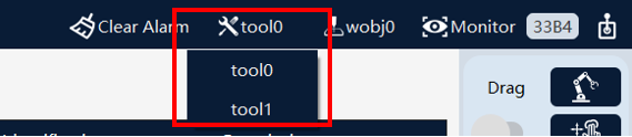
Used during Jog:
If it is necessary to use a special tool for Jog operation, select the desired tool in the drop-down list of the 'Tool' in the menu on the upper side of the teach pendant interface.
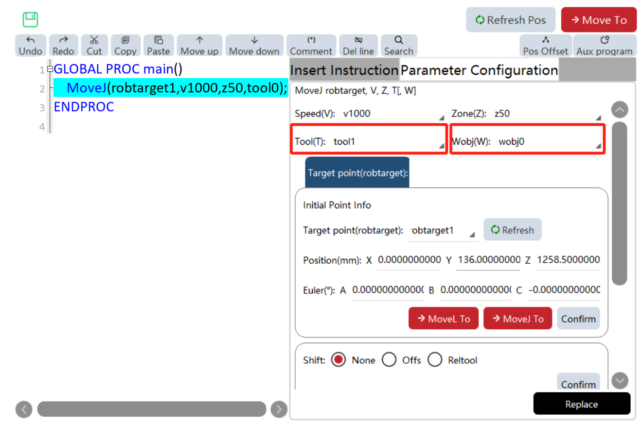
Used in the RL program:
It is very simple to use a special tool in the program, and you just need to use the desired tool in the "Tool" parameter of the motion statement. When the "Aux Program" interface of the teach pendant is used to write motion commands, the default "Tool" and "Wobj" are tool0 and wobj0.
8.12.2.7 External tools and handheld tools
In most cases, a tool is installed on the robot, and the tool moves with the robot to complete specified work. Such a tool is called handheld tool. Typical handheld tools include: grippers, suction cups, and welding guns.
In certain specific situations, installing a tool onto the robot may affect its normal usage, such as during grinding or gluing. In these cases, it would be more appropriate to mount the work object on the robot and fix the tool at a specific external location. We call these tools that are installed outside the robot and fixed at a certain location external tools (some brands call them Stationary Tool or Remote TCP), and the corresponding work objects are called handheld work objects.
8.12.3 Operation examples
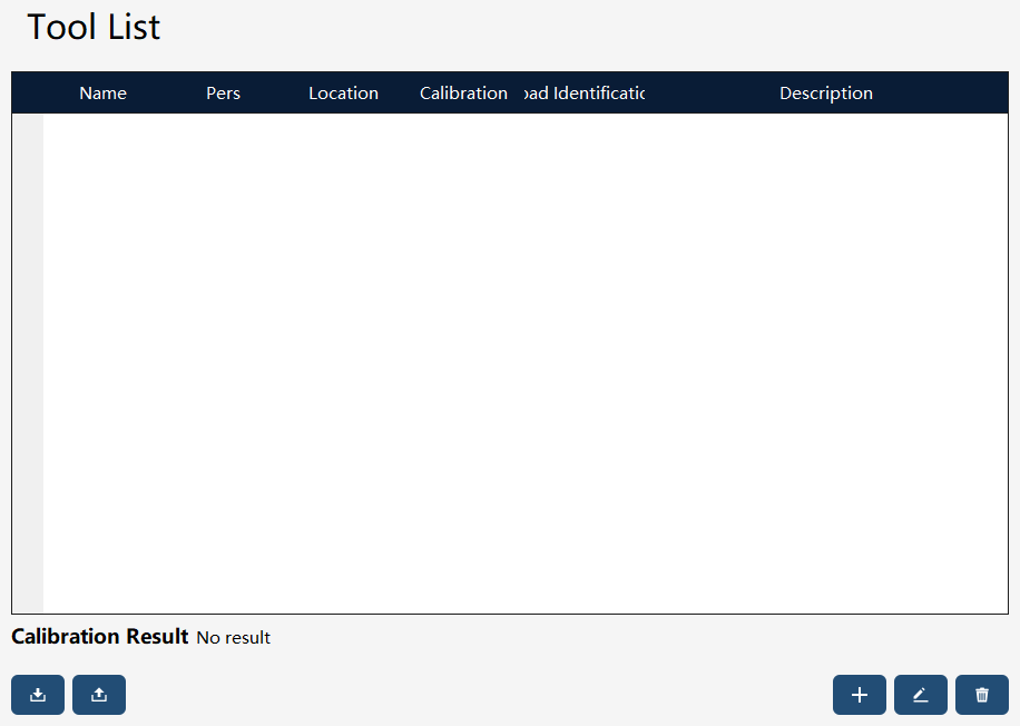
8.12.3.1 New handheld tool
Before the calibration of tool frame, the user needs to prepare a fixed external point, which shall be located within the robot’s working range and can be contacted by the calibrated tool in a very flexible orientation.

Operation |
Graphical Representation |
Explanation |
1. Click "+" in the bottom right corner of the tool list to enter the New Tool wizard interface. |
|
Users with the permission level of "Programmer" or above can perform creation and edit operations. |
2. Set the tool attribute: Robot hold. |
|
|
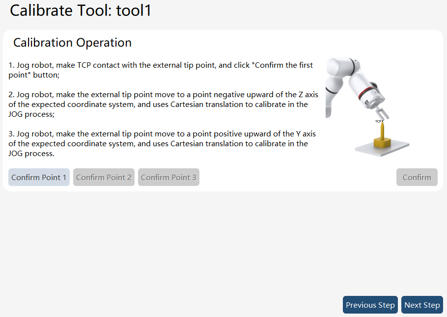
3. Pose calibration, taking the three-point method as an example: Select "Calibrate now" and set the calibration method to "3 Points". Then, click the "Perform calib" button to enter the "New User Frame" page to perform the calibration. |
|
Jog the robot to move the calibrated tool TCP to the points of the desired frame in sequence: the origin, a point on the x-axis, and a point on the xy-plane or on the y-axis, and click the "Confirm Point 1", "Confirm Point 2", and "Confirm Point 3" buttons accordingly. After confirming all three points, click the "Confirm" button to return to the "New Tool" page, where the "Calibration Status" will now be displayed as "Calibrated." When the four-point method is used to calibrate the tool origin, the orientation differences between the four points shall be as large as possible. In other words, the robot shall try to contact the external point in different orientations. |
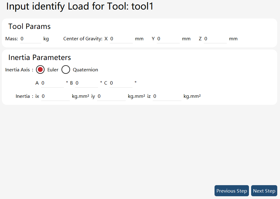
4. Load identification (taking manual input as an example): Select "Manual Input, " click the "Perform manual input" button, and enter the "Tool Load Identification" page. |
|
Input the physical information of the tool, click the "Next Step" button, and return to the "New Tool" page. At this point, the "Identify status" will be displayed as "Identified". |
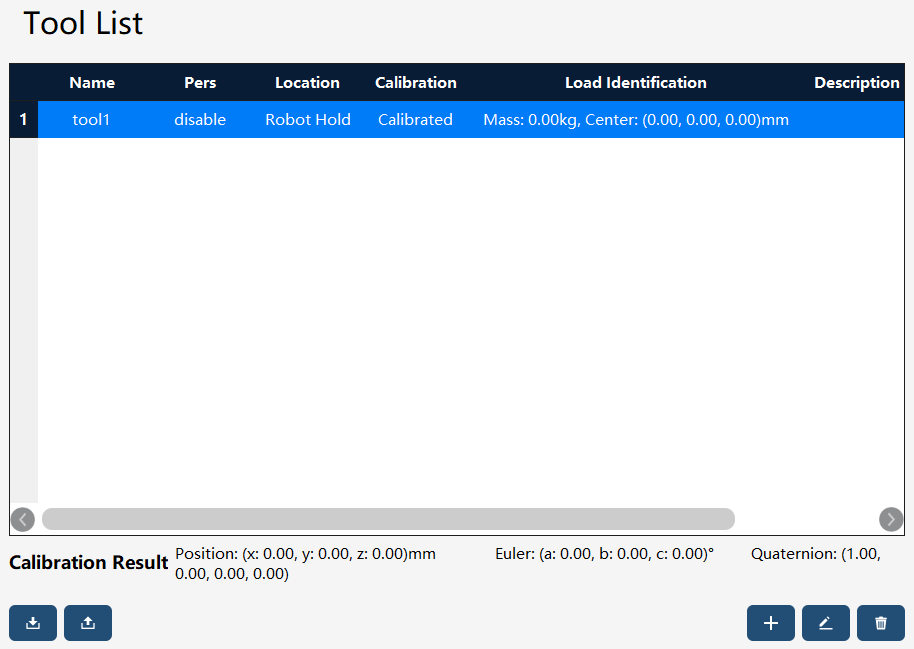
5. Click the "Next" button to complete the creation of the new external work object. |
|
The newly created external work object will be displayed in the work object list. |

8.12.3.2 New external tool
The calibration methods for external tools are consistent with those for handheld tools, supporting three methods: six-point method, four-point method, and three-point method.
Attention: To calibrate the external tool frame, it is necessary to use the already calibrated handheld tool.
Operation |
Graphical Representation |
Explanation |
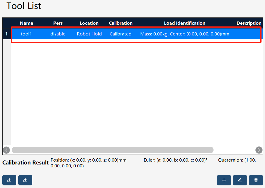
1. If a calibrated handheld tool already exists in the list, it can be used to assist in the calibration of an external tool. In this example, we will use "tool1" as the reference. |
|
The external tool to be calibrated shall have a tip. |
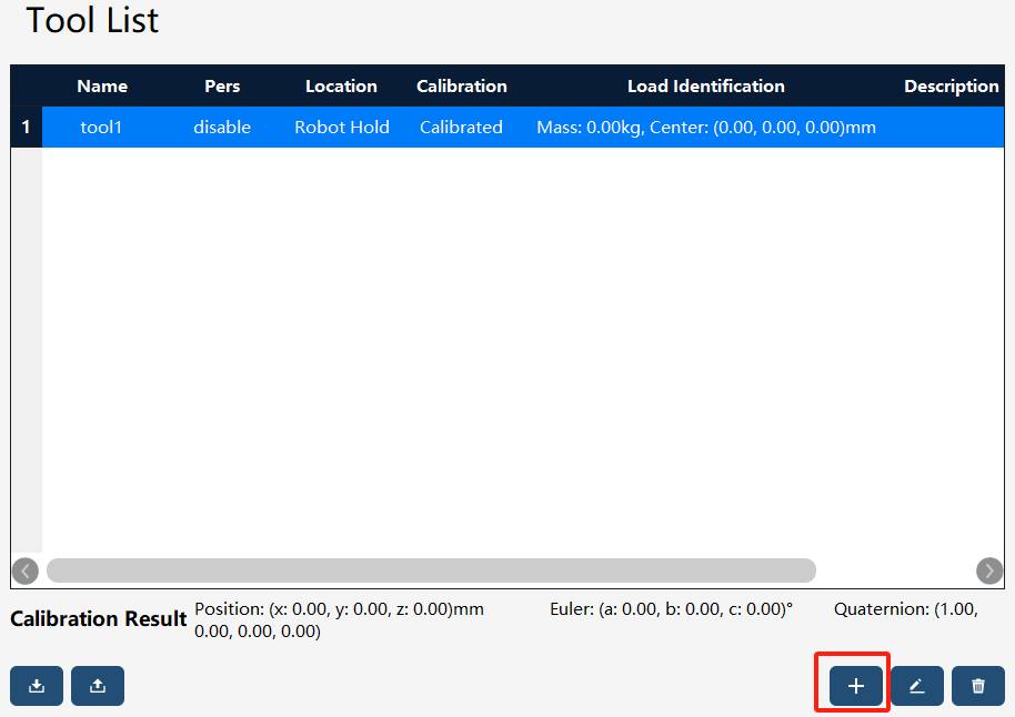
2. Click "+" in the bottom right corner of the tool list to enter the New Tool wizard interface. |
|
Users with the permission level of "Programmer" or above can perform creation and edit operations. |
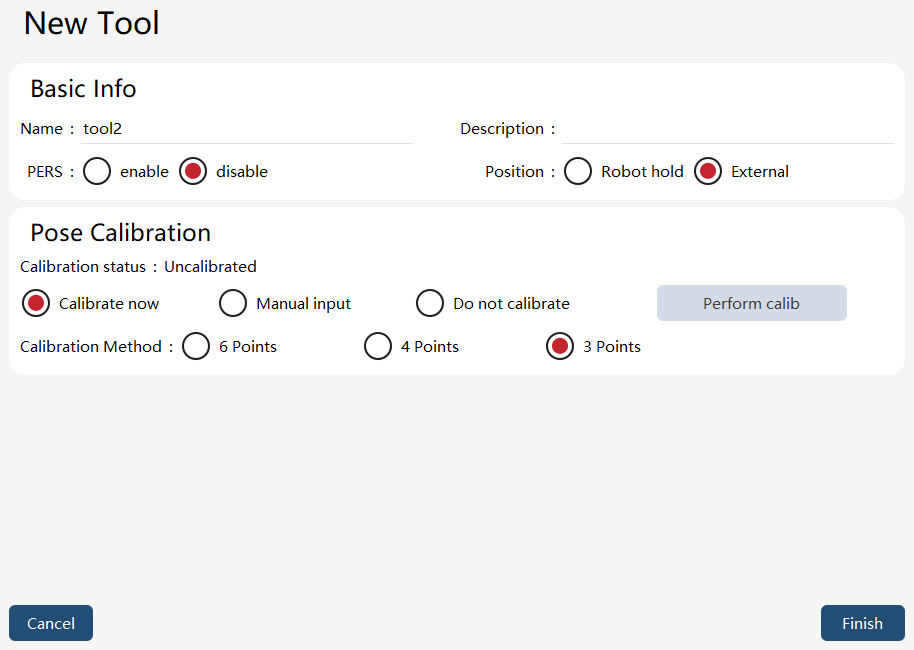
3. Set the tool attribute: External. |
|
|
4. Switch between tools in the upper right corner and select the already calibrated handheld tool, "tool1". |
|
|
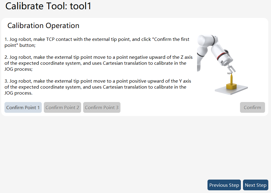
5. Pose calibration, taking the four-point method as an example: Select "Calibrate now" and set the calibration method to "4 Points". Then, click the "Perform calib" button to enter the "Tool Calibration" page to perform the calibration. |
|
Jog the robot so that the TCP of the calibrated tool can point at the origin of the desired work object frame in different orientations, and then confirm the first, second, third, and fourth points respectively. The orientation difference between the 4 points shall be as large as possible, which means the robot shall try to contact the external point in different orientations. After the calibration is completed, the system will pop up the calibration error. Select whether to re-calibrate according to the error situation (refer to the confirmed calibration accuracy). |

Note:
The external tool must be used together with the corresponding work object, meaning among the Position parameters which are selected at the same time in the tool and work object respectively, one must be External while the other be Robot hold. Otherwise, the system will prompt an error and forbid jogging the robot.
The reference frames for defining tool frames and work frames of external tools differ from those for defining tool frames and work frames of normal tools. You can refer to the following table.
Frame name |
Definition of a normal tool relative to … |
Definition of an external tool relative to … |
Work object frame |
User frame |
User frame |
User frame |
World frame |
Flange frame |
Tool frame |
Flange frame |
World frame |
8.12.3.3 Use of TCP correction
Before using the TCP correction function, prepare a fixed external tip point that must be within the robot’s working range and accessible by the tool to be calibrated in a relatively flexible orientation.
Operation |
Graphical Representation |
Explanation |
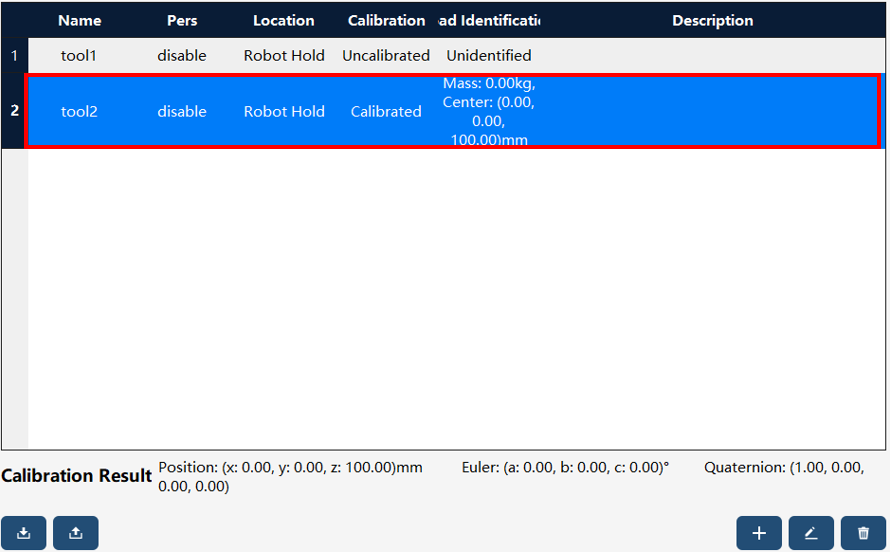
1. In the tool list interface, select the tool that needs correction and click the "Edit" button in the lower right corner to enter the Edit Tool wizard interface. |
|
Users with the permission level of "Programmer" or above can perform creation and edit operations. The external tool to be calibrated shall have a tip. The tool needs to be calibrated and have its load set, and it must be a handheld tool. |
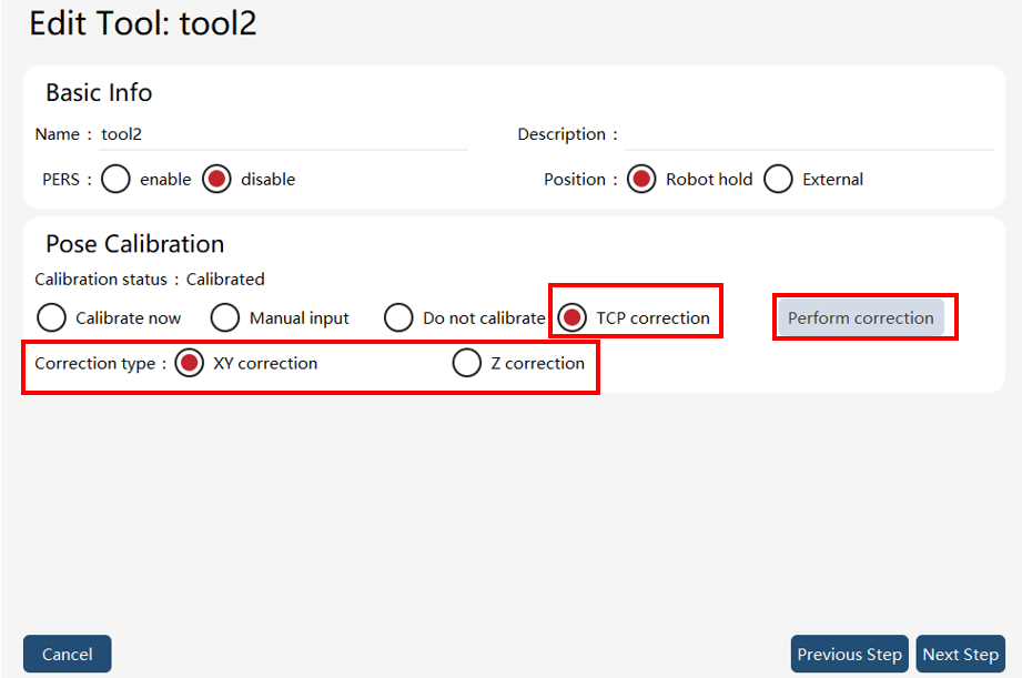
2. Using "XY correction" as an example.Enter the pose calibration interface. Select the "TCP Correction" button, choose the correction type, and then click the "Execute Correction" button to enter the specified type of TCP correction interface. |
|
TCP correction supports two types of corrections: "XY Correction" and "Z Correction". "XY Correction": Correct the X and Y parameters of the tool’s TCP position. "Z Correction": Correct the Z parameter of the tool’s TCP position. |
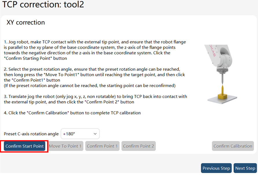
3. Adjust the tool’s pose and confirm the TCP correction starting point |
|
Jog the robot so that the tool tip contacts the external tip, ensuring that the robot flange is parallel to the world frame’s XY plane and the flange’s Z axis points in the negative direction of the world frame’s Z axis. Then, click the "Confirm Starting Point" button. |
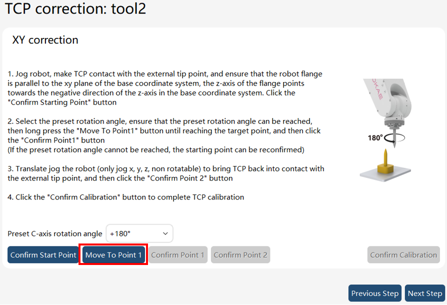
4. Set the preset rotation angle and move to the first point |
|
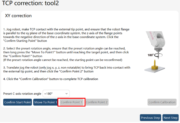
Select a preset rotation angle, ensuring that it is reachable. Then, long-press the "Move to First Point" button until the target point is reached. (If none of the preset rotation angles are reachable, reconfirm the starting point) |
5. Confirm the first point of TCP correction |
|
After the robot moves to the target point, click the "Confirm First Point" button. |
6. Confirm the second point of TCP correction |
|
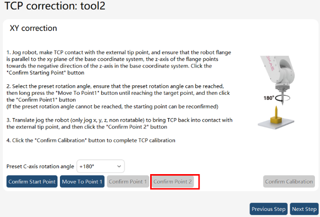
Jog the robot in translation (only jog X, Y, Z; no rotation) so that the tool tip contacts the external tip point again, and then click the "Confirm Second Point" button. |
7. Confirm correction and set correction result |
|
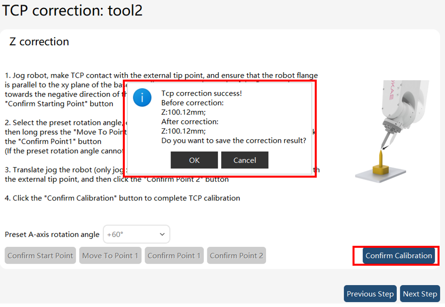
Click the "Confirm Correction" button to complete the TCP correction. The interface displays a pop-up window showing the TCP correction result. Click the "Confirm" button to set the tool’s TCP to the corrected result, or click "Cancel" to keep the tool’s TCP as it was before correction. |
8.12.4 Tool export/import
8.12.4.1 Tool export
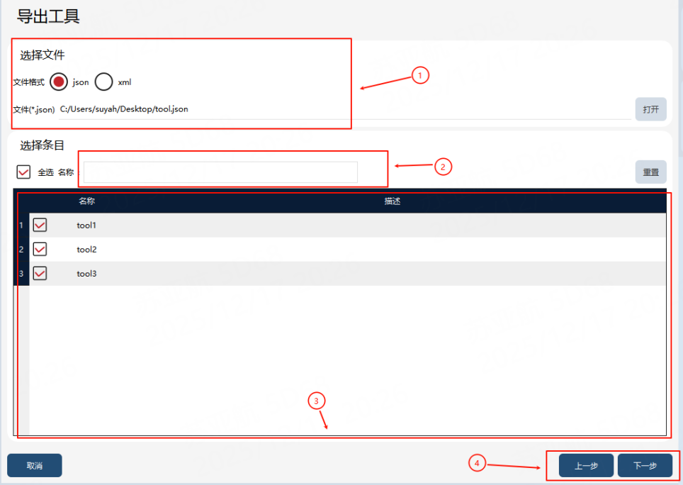
On the tool list page, click the button at the bottom left to enter the tool export interface.
① |
Tool export target file (including path) |
② |
Filter box |
③ |
Tool list |
④ |
Tool export button |
Export steps: First, input or select the path for the tool export target file in ①, and filter by name in ②, if necessary. Then, check the tools to be exported in ③. Finally, click the "Next" button in ④ to execute the export, and the exported tool file will be generated in the path specified in ①.
8.12.4.2 Tool import
On the tool list page, click the button at the bottom left to enter the tool import interface.
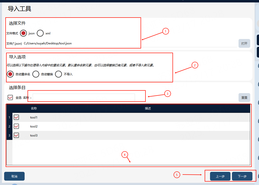
① |
Tool import file |
② |
Tool import option, which is the strategy for handling entry conflict |
③ |
Filter box |
④ |
Tool import entry |
⑤ |
Tool import button |
Import steps: First, select the tool file to be imported in ①, and filter by name in ③, if necessary. Then, select the conflict handling strategy in ② and the tools to be imported in ④. Finally, click the "Next" button in ⑤ to execute the import, and the selected tools will be imported locally.