Custom production
The custom production interface provides a simple and intuitive interactive mode for users. Users can create a concise monitoring and interaction interface simply by selecting registers, DI/DO signals, points, and project variables of interest.
The functions supported by this interface include: displaying and editing registers, displaying the status of DI signals, enabling DO signals, updating point positions, and displaying and editing project variables.
Overview
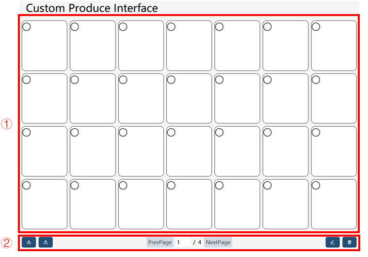
① |
The Operation/Display Panel mainly includes the selection, display, and operation of different controls. The currently selectable controls include single DI, single DO, point position update, registers, and project variables. |
② |
Interface editing column. It involves data export from and import to the custom production interface, page switching, and individual control editing and deletion. |
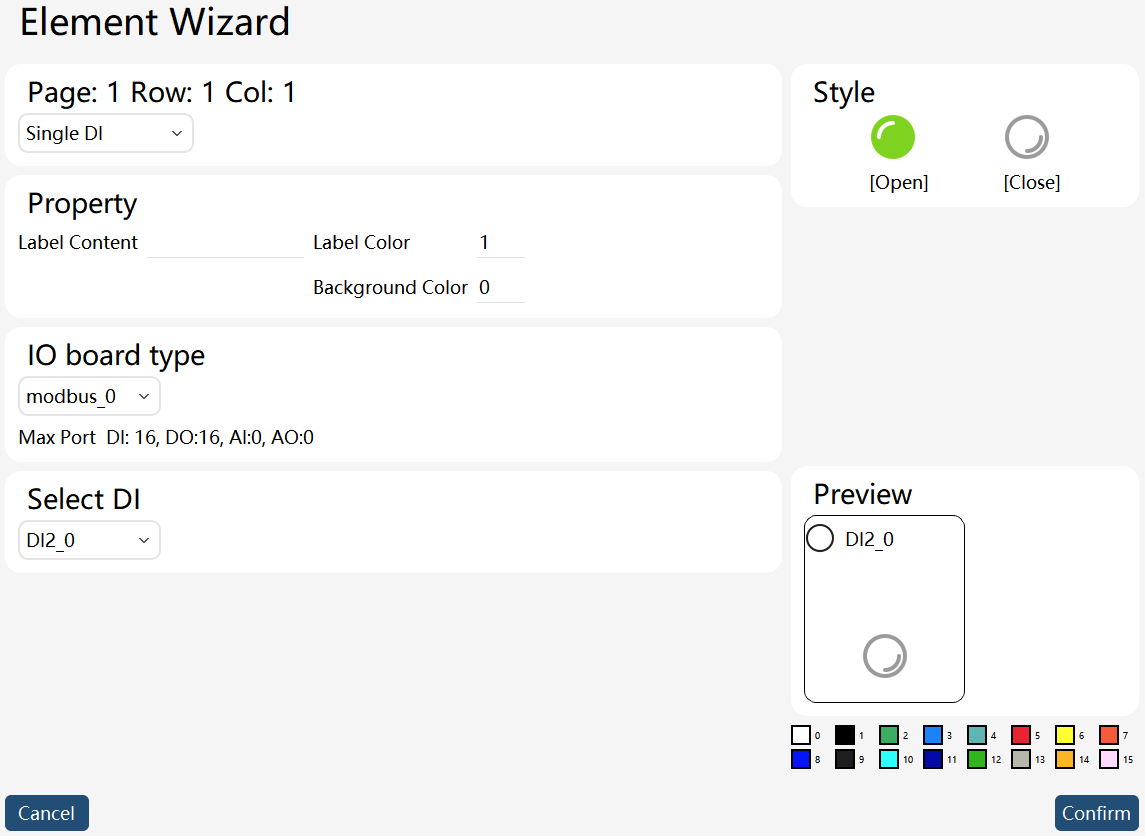
The Operation/Display Panel contains multiple production task controls, which can be imported, exported, edited, and deleted through the buttons below.
The control contains three parts, among which the top part shows the control signal name, the middle part refers to the control’s label text (customized by users), and the bottom part is available for users' operations/displays on the control. Various controls provide different interactions.
Basic operations
Operation |
Graphical Representation |
Explanation |
Control selection |
|
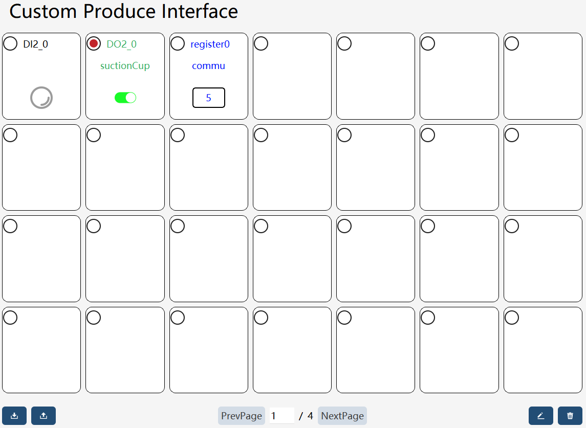
Clicking the circle in the top left corner of a control allows you to select it on the interface, and the circular frame in the top left corner of the selected control will turn red. For instance, the currently selected control on the interface is the "suctionCup" control in the first row and second column. |
Import |
|
Click the |
Export |
|
Click the |
Edit |
|
Click the |
Delete |
|
Click the |




Control introduction
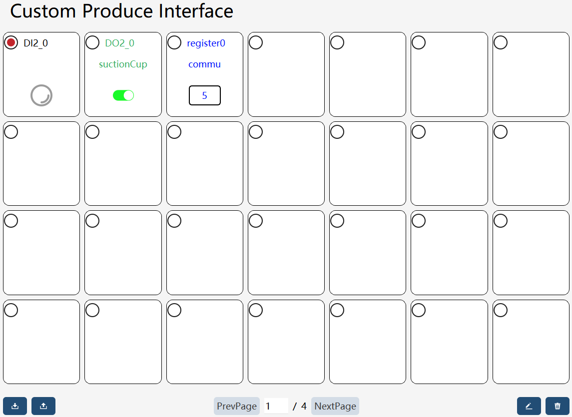
With four types of controls offered by the custom production interface, users can develop the interface style suited for the production conditions. They are the single DI control, single DO control, register control, and PERS variable control, respectively. The control editing page is shown below.
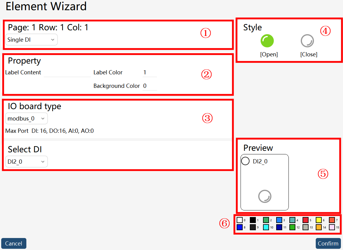
① |
Select the control type, including: single DI, single DO, register, PERS variable, and none. |
② |
General attributes, including: label text, label color, and background color. See ⑥ for the representative label colors. |
③ |
Special attributes, which are different for each control. See below for details. |
④ |
Pattern bar, providing the data expression pattern shown by various controls. |
⑤ |
Preview bar, where you can preview the final style effect of the current edited control. |
⑥ |
16 colors are available, and you can enter the desired color number in ②. |
Single DI control
Single DI control can be used for DI display. Types of optional IO boards include: (1) IO devices configured by users on the IO Device interface; and (2) User DI signals configured by users in the project’s IO signal list.
The editing interface is shown below:
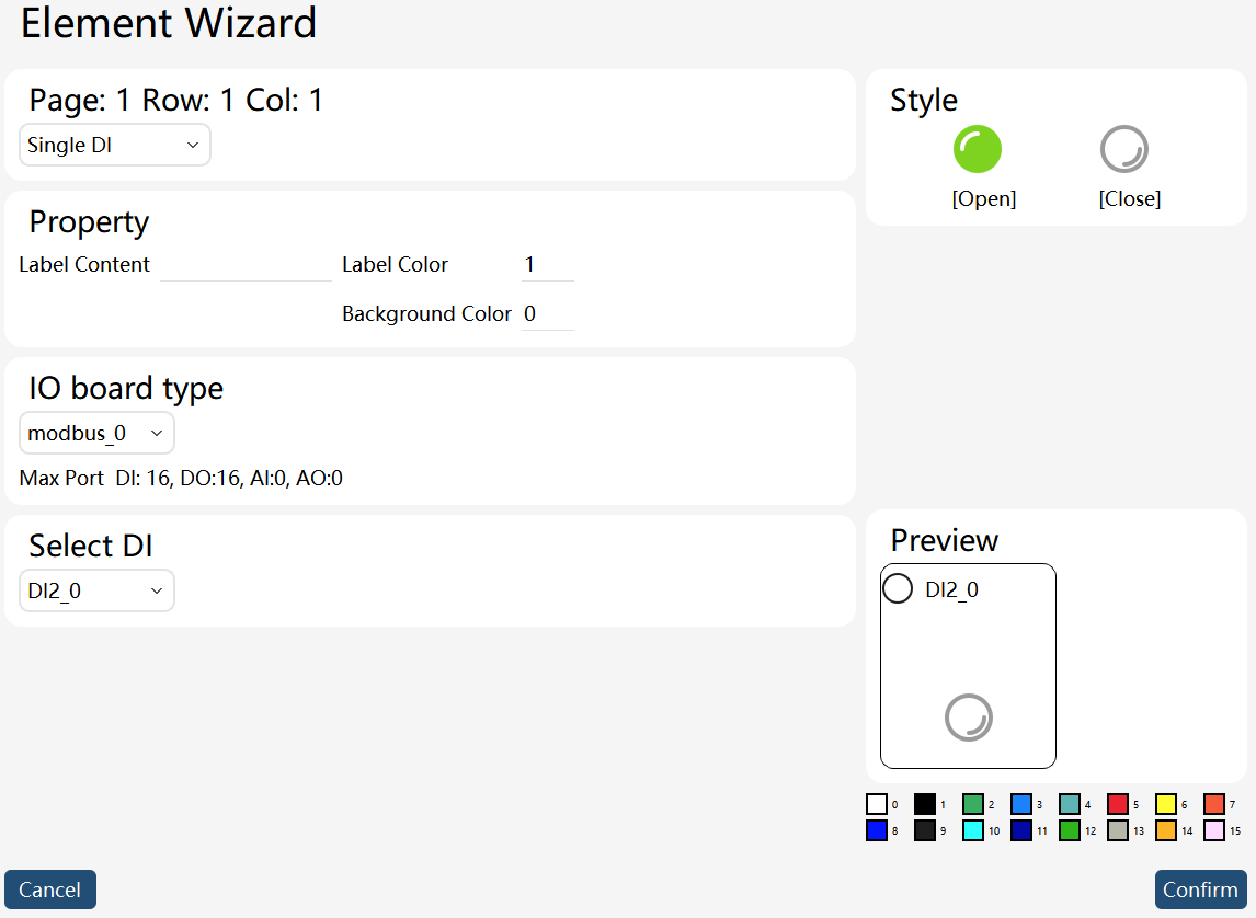
When the selected DI is True, the "On" icon under the control pattern is green. When the IO is False, the "Off" icon under the control pattern is gray.
The single DI control is not available for control interaction and is only used for DI status display.
Single DO control
Single DO control can be used for DO signal display and settings. Types of optional IO boards include: (1) IO devices configured by users on the IO Device interface; and (2) User DO signals configured by users in the project’s IO signal list.
The editing interface is shown below:
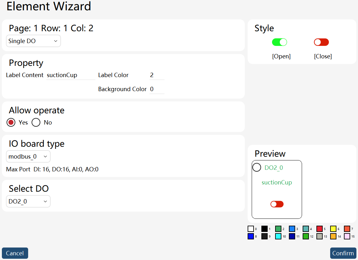
When the selected IO is True, the "On" icon under the control pattern is green. When the IO is False, the "Off" icon under the control pattern is red.
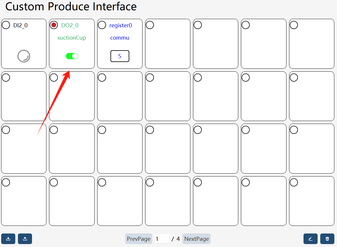
The single DO control provides button on/off interaction, and the "Allow Operation" attribute can be used to set whether a control can be operated on the "Operation/Display Panel".
Click the button within the red frame in the "Operation/Display Panel" interface to operate the DO signal.
Register control
Register controls can monitor and modify the register values configured under "Communication" - "Registers". Registers can be filtered by "Bus device".
Attention: The register control does not support the register array type.
The editing interface is shown below:
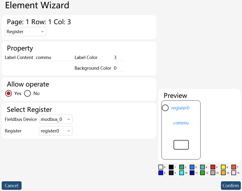
The register control does not provide a status-style display, but it can display the register value.
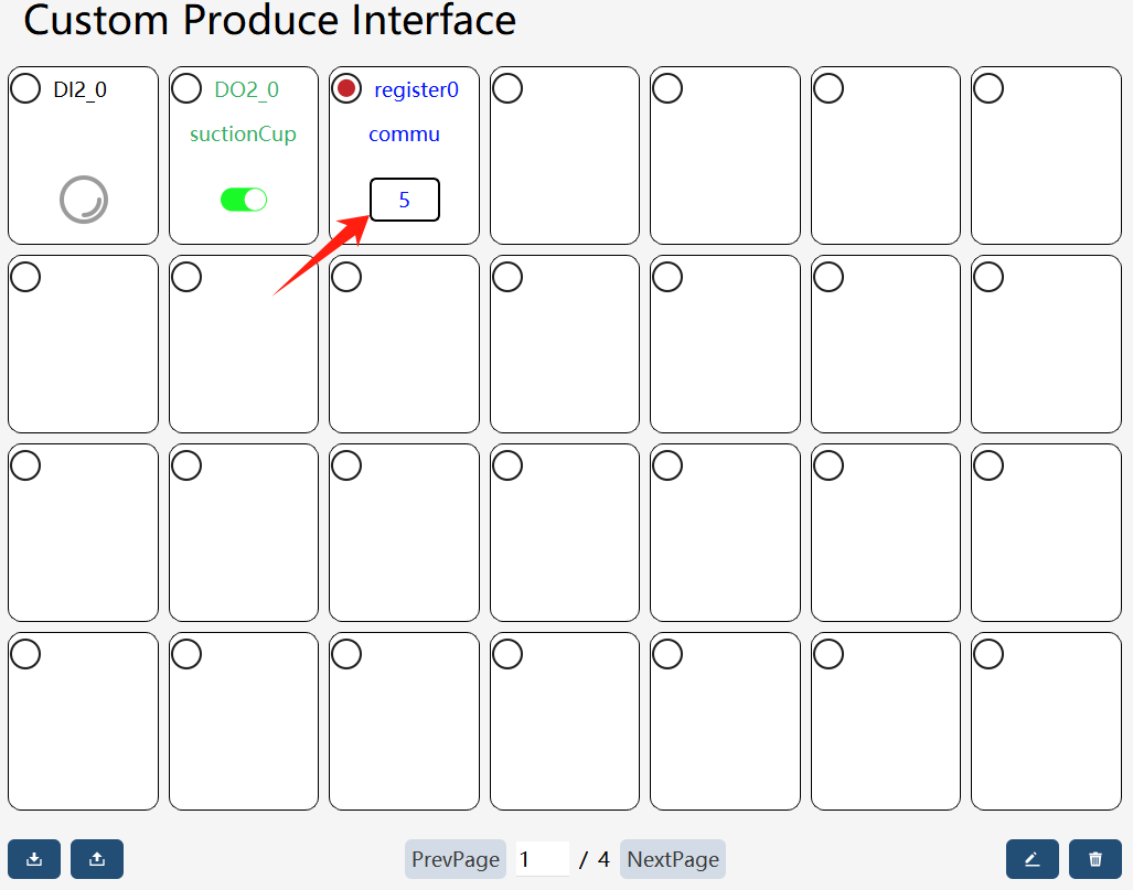
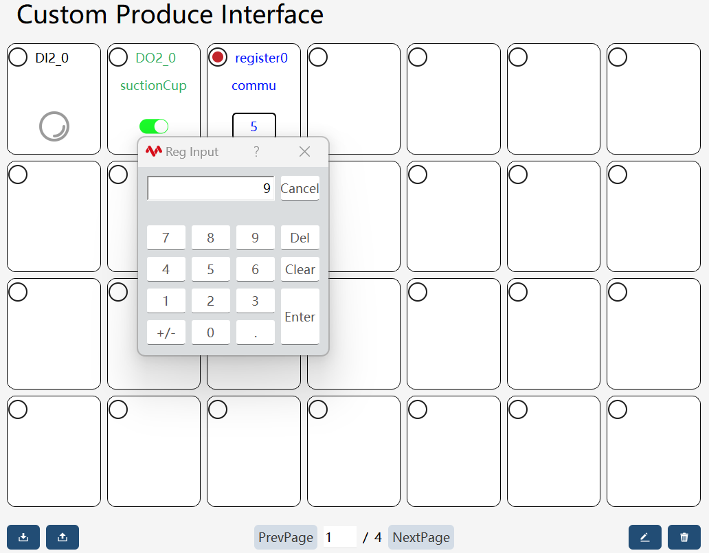
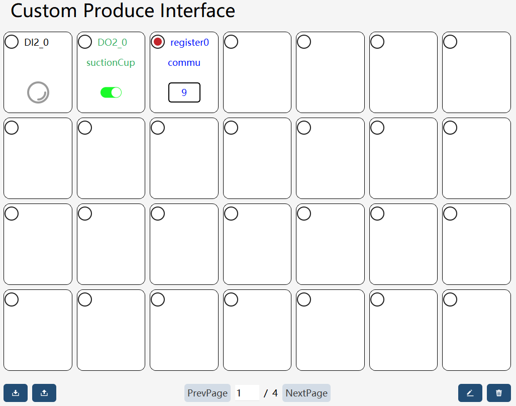
The register control is edited by entering values using a numeric keyboard. On the "Operation/Display Panel" interface, you can click on the value "Display/Edit Box" for the value to enter the register value (attention: writing is only allowed when the register is set to "Write-only" mode).
Value writing steps:
| Step | Graphical Representation | Explanation |
|---|---|---|
1. Selection |
|
Click on the value display/editing box in the register control. |
2. Input |
|
Input the register value to be set. |
3. Successful value writing. |
|
Point position update control
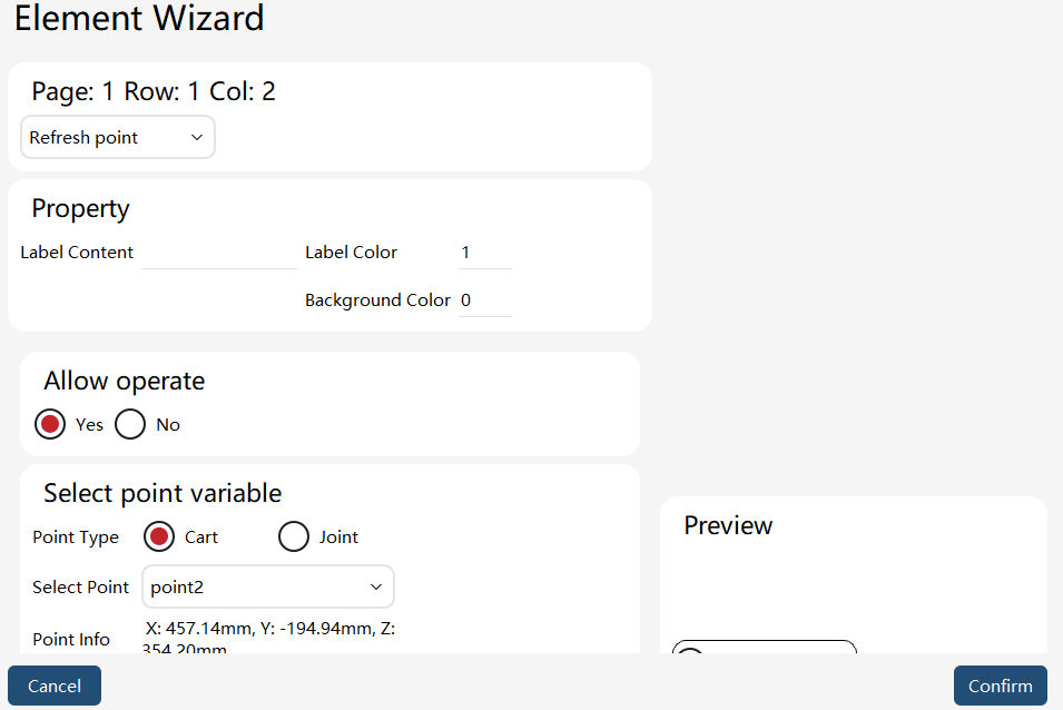
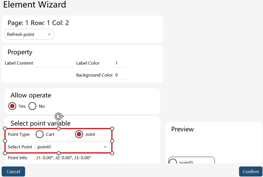
The point position update control can modify point information in the point list, with selectable point types including Cartesian and joint.
The editing interface is shown below:
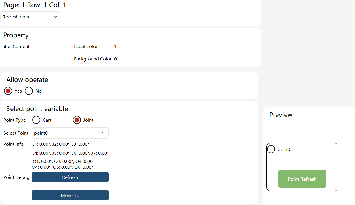
The point position update control does not provide status style display but offers an "Update Position" button.
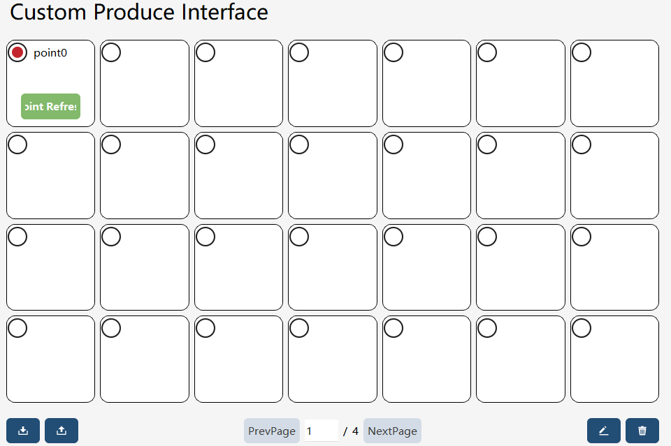
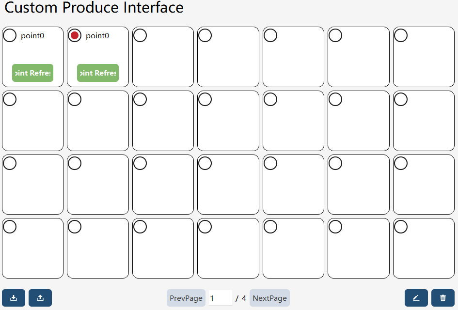
Clicking the "Update Position" button on the "Operation/Display Panel" interface allows you to update the values of the selected point.
Steps for updating point position:
| Step | Graphical Representation | Explanation |
|---|---|---|
1. Selection |
|
Select an empty control |
2. Select the point position update function |
|
|
3. Select the point whose position needs to be updated |
|
Support both Cartesian and joint point types |
4. Complete |
|
Click "Complete" to update the point position in the custom production interface |
Project variable control
The project variable control can monitor and modify the variables configured under "Project" - "Variable List". The selectable variable types include int, byte, bool, and double. Variable array types are not supported.
The editing interface is shown below:
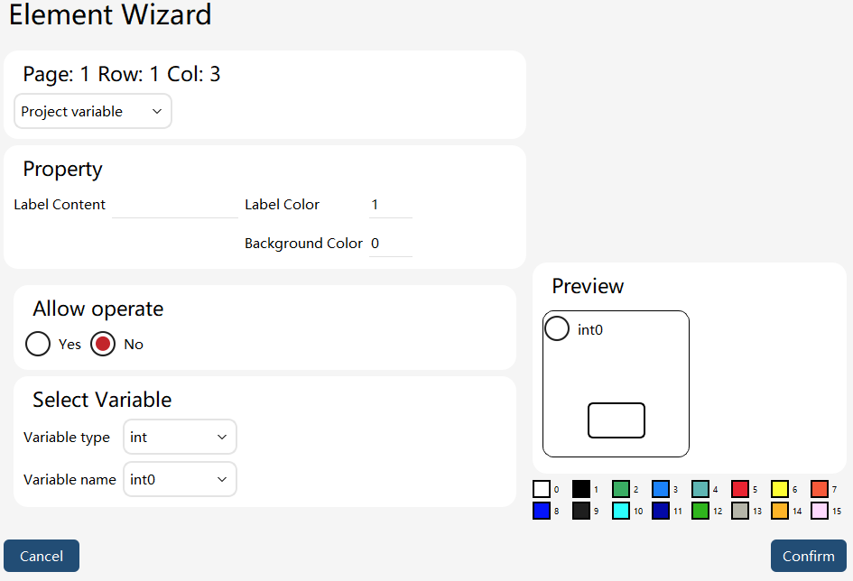
The project variable control does not provide a status-style display, but it can display the project variable values.
The project variable control is edited by entering values using a numeric keyboard. The "Allow Operation" attribute can be used to set whether the control can be operated on the "Operation/Display Panel".
Click the value display/editing box on the "Operation/Display Panel" interface to write values to project variables.
Value writing steps:
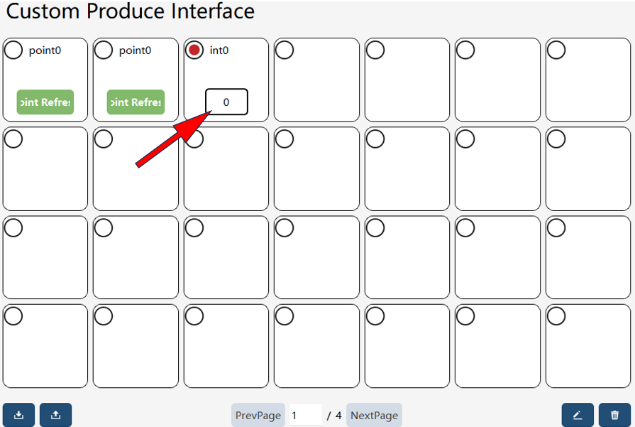
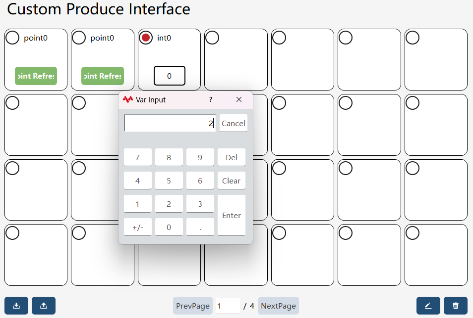
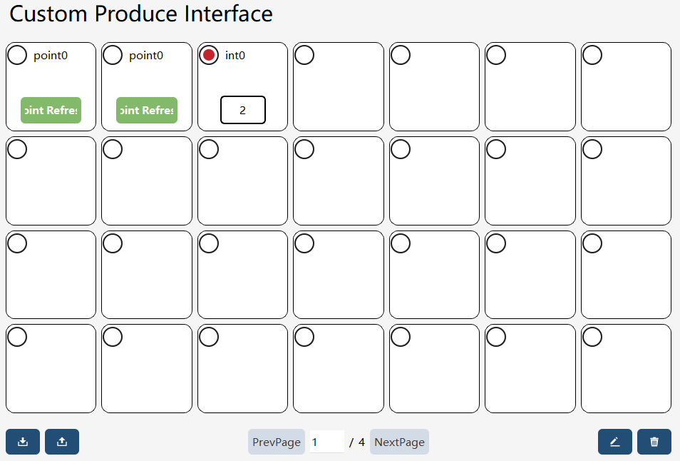
| Step | Graphical Representation | Explanation |
|---|---|---|
1. Selection |
|
Click the value display/editing box in the project variable control |
2. Input |
|
Input the project variable value to be set |
3. Successful value writing. |
|
Custom production export/import
Custom production export
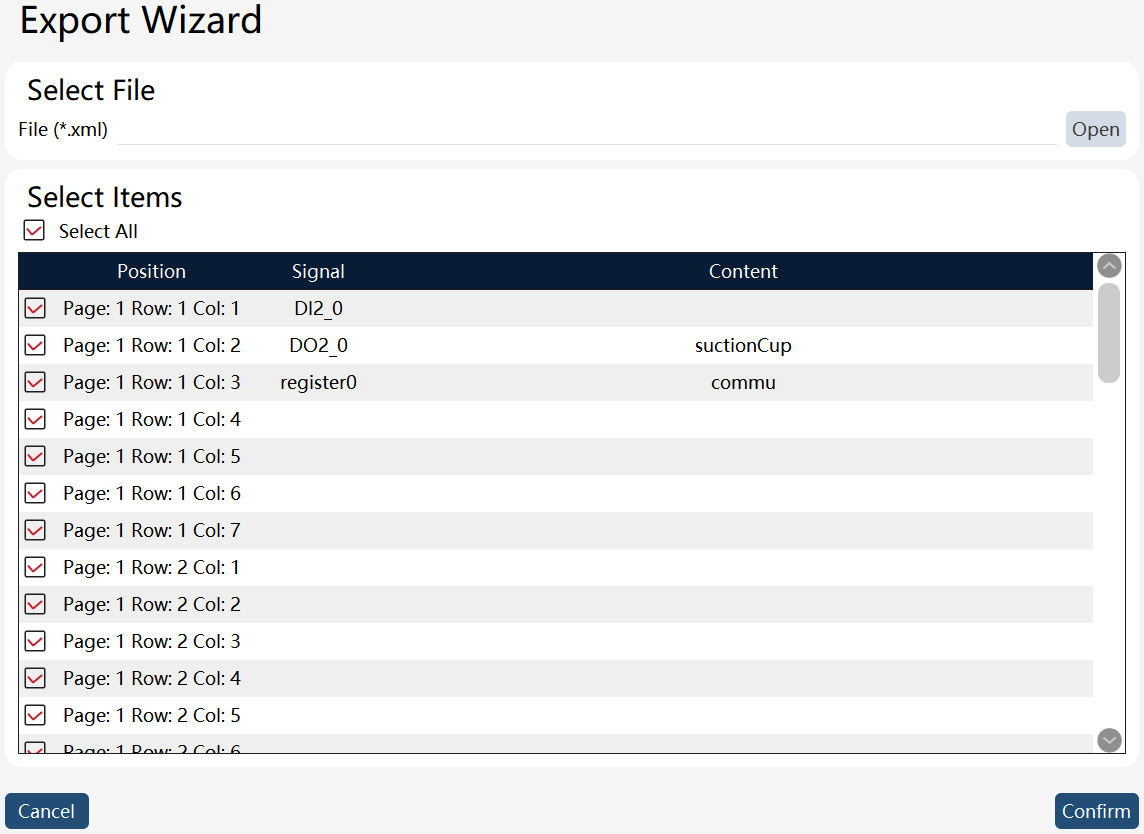
On the custom production page, click theimage::en/image269.png[width=700,align=center] button at the bottom left to enter the custom production export interface.
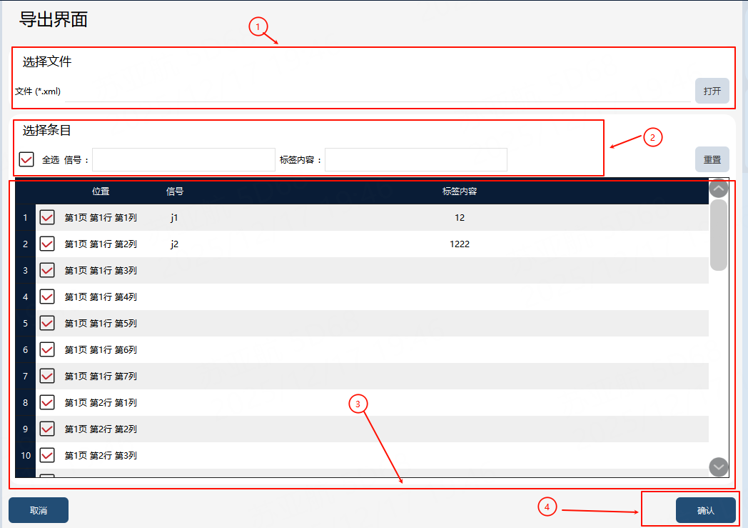
① |
Custom production export target file (including path) |
② |
Filter box |
③ |
Custom production export selection list |
④ |
Custom production export button |
Export steps: First, input or select the path for the custom production export target file in ①, and filter by name in ②, if necessary. Then, check the entries to be exported in ③. Finally, click the button in ④ to execute the export, and the exported file will be generated in the path specified in ①.
Custom production import
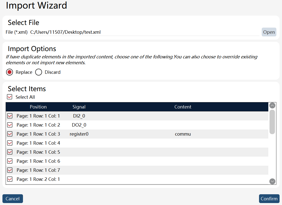
On the custom production page, click theimage::en/image271.png[width=700,align=center] button at the bottom left to enter the custom production import interface.
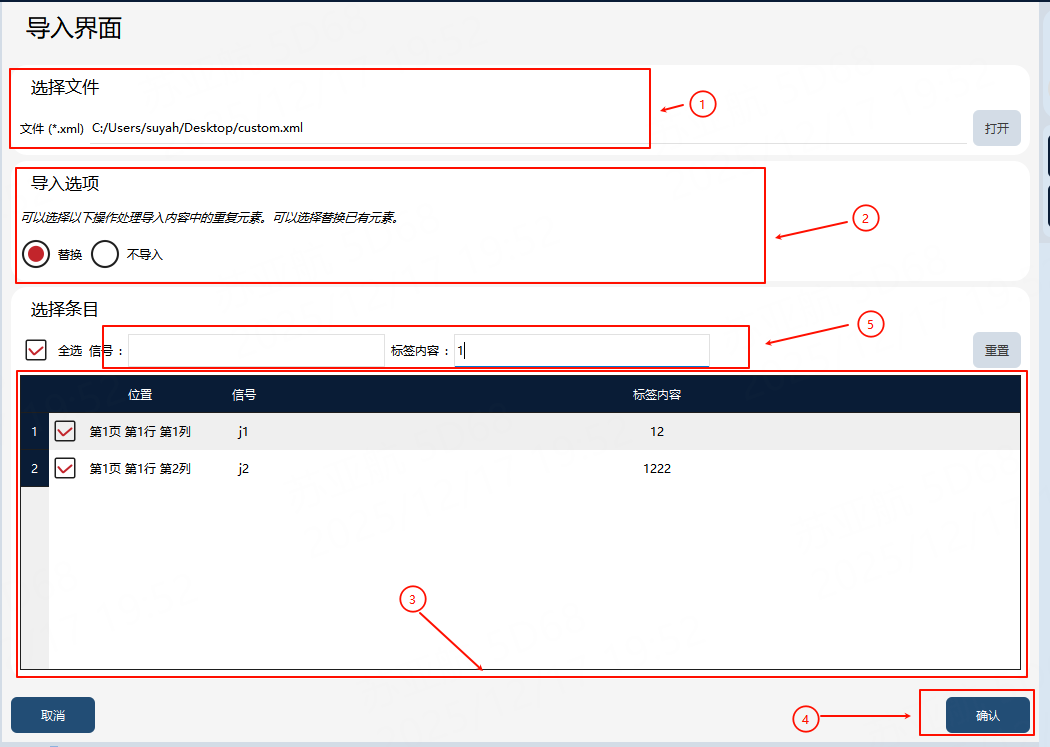
① |
Custom production import file |
② |
Custom production import option, which is the strategy for handling entry conflict |
③ |
Custom production import entry |
④ |
Custom production import button |
⑤ |
Filter box |
Import steps: First, select the custom production file to be imported in ①. Then, select the conflict handling strategy for imported entries in ② and the entries to be imported in ③. Finally, click the button in ④ to execute the import, and the selected custom production will be imported locally.