8.13.1 Overview
Work object refers to the object that is processed or handled by a robot with a tool.
The xCore system uses wobj (Work Object) type variables to describe an actual work object. Defining a work object means creating a wobj variable.
The motion trajectories of robots are defined within the work object frame for two good reasons:
(1) When the work object moves or multiple identical work objects are being processed, the user only needs to recalibrate the work object frame, and all the paths in the program can be updated accordingly without the need to rewrite all paths in the program;
(2) It allows the processing of the work objects that are moved by an additional axis (such as positioner).
Each work object is jointly defined by two frames: one is user frame, which can be understood as the workbench/table where the work object is placed and is particularly useful when multiple identical work objects are handled; and the other is work object frame, which can be interpreted as the work object itself on the workbench. The path points of the robot are described based on the tool position relative to the work object position.
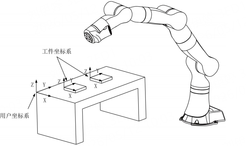
For using the external tool function, the corresponding work object shall be installed on the robot. In this case, the work object is called handheld work object. The handheld work object also needs the calibration of the work object frame and must use the calibrated external tool for calibration. For more details, please refer to the external tool function.
|
Wobj0 is a work object variable pre-defined by the system, and both its user frame and work object frame coincide with the world frame. Same as tool0, wobj0 cannot be modified as well. For PCB 3- or 4-axis robots, the work object frame only supports manual input. The components of orientation A and C are set to 0, and manual user modification is prohibited. |
8.13.2 Use of work object frame
Used during Jog:
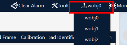
If it is necessary to perform Jog operation in a special work object frame, select the desired work object in the drop-down list in the menu on the upper side of the teach pendant interface.
Used in the RL program:
It is very simple to use a special work object in the program, and you just need to use the desired work object in the "Wobj" parameter of the motion statement. When programming the motion commands on the "Aux Program" interface of the teach pendant, the "Tool" and "Wobj" in default are consistent with those used during Jog operation, which are the currently selected "Tool" and "Wobj" in the menu on the upper side of the interface are currently selected. For the detailed operation steps, please refer to Insert Command.
|
Generally, the work object parameter for the motion command is optional. Therefore, unless otherwise specified, the system will use wobj0 by default, which coincides with the world frame. To use the external tool function, all work object parameters corresponding to the tools must be designated. |
8.13.3 Operation examples
8.13.3.1 New external work object
To calibrate the external work object frame, it is necessary to use the already calibrated handheld tool for assistance.
Operation |
Graphical Representation |
Explanation |
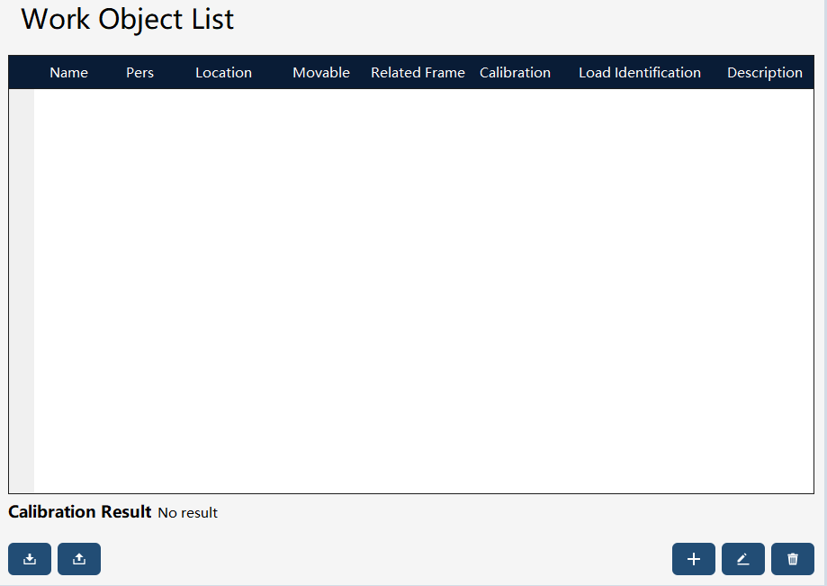
1. Click "+" in the bottom right corner of the work object list to enter the New Work Object wizard interface. |
|
Users with the permission level of "Programmer" or above can perform creation and edit operations |
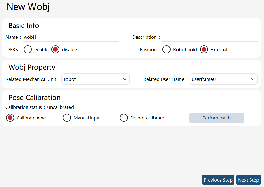
2. Set the work object attribute to external. |
|
|
3. Switch the tool in the upper right corner to the already calibrated handheld tool, "tool1" |
|
|
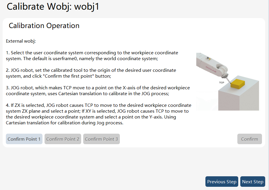
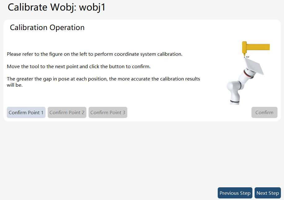
4. Click the "Perform Calibration" button to enter the work object calibration interface. |
|
Jog the robot to point the calibrated tool TCP to the desired origin of the work object frame, and click the "Confirm Point 1" button. Then, Jog the robot to point the TCP to a point on the desired X-axis of the work object frame, and click the "Confirm Point 2" button. After that, Jog the robot to point the TCP to a point on the desired Y-axis of the work object frame, and click the "Confirm Point 3" button. Finally, click "Confirm Calibration" to bring up a dialog box for confirming the calibration results, and click "Confirm." Then, Click the "Next" button to return to the "New Work Object" page. |
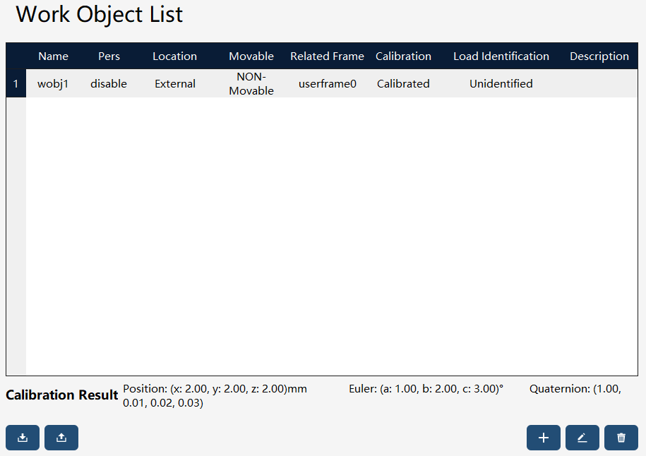
5. Click the "Next" button to complete the creation of the new work object. |
|
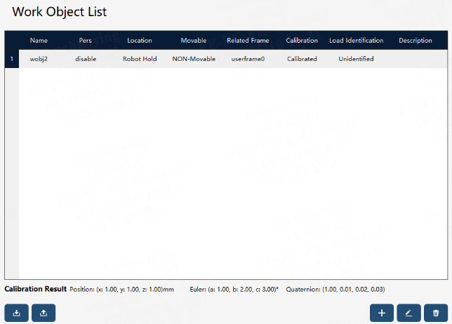
The newly created work object will be displayed in the work object list. |

8.13.3.2 New handheld work object
To calibrate the handheld work object frame, it is necessary to use the already calibrated external tool for assistance.
Operation |
Graphical Representation |
Explanation |
1. Click "+" in the bottom right corner of the work object list to enter the New Work Object wizard interface. |
|
Users with the permission level of "Programmer" or above can perform creation and edit operations. |
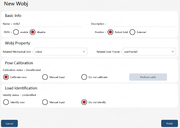
2. Set the work object attribute: handheld |
|
"External" refers to the case where the work object is not fixed relative to the end-effector of the robot, while "handheld" means the case where the work object is fixed relative to the end-effector of the robot. |
3. Switch the tool in the upper right corner to the already calibrated external tool, tool2 |
|
|
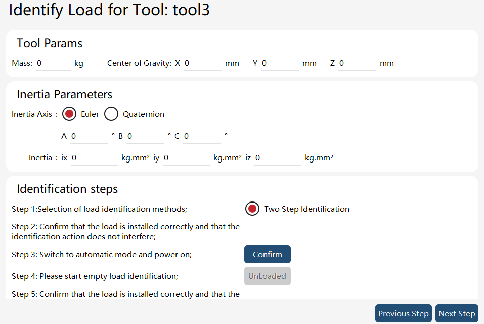
4. Load identification is equivalent to tool load identification |
|
|
5. Click the "Execute Calibration" button to enter the work object calibration interface. |
|
Jog the robot to point the calibrated tool TCP to the desired origin of the work object frame, and click the "Confirm Point 1" button. Then, Jog the robot to point the TCP to a point on the desired X-axis of the work object frame, and click the "Confirm Point 2" button. After that, Jog the robot to point the TCP to a point on the desired Y-axis/XOY-plane of the work object frame, and click the "Confirm Point 3" button. Finally, click "Confirm Calibration" to bring up a dialog box for confirming the calibration results, and click "Confirm." Then, Click the "Next" button to return to the "New Work Object" page |
6. Click the "Next" button to complete the creation of the new work object |
|
The newly created work object will be displayed in the work object list. |

8.13.4 Work object export/import
8.13.4.1 Work object export
On the work object list page, click theimage::en/image269.png[width=700,align=center] button at the bottom left to enter the work object export interface.
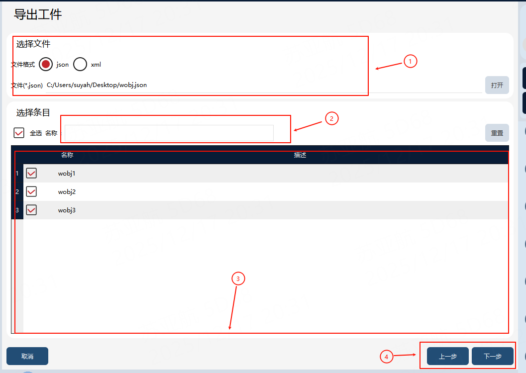
① |
Work object export target file (including path) |
② |
Filter box |
③ |
Work object list |
④ |
Work object export button |
Export steps: First, input or select the path for the work object export target file in ①, and filter by name in ②, if necessary. Then, check the work objects to be exported in ③. Finally, click the "Next" button in ④ to execute the export, and the exported work object file will be generated in the path specified in ①.
8.13.4.2 Work object import
On the work object list page, click theimage::en/image271.png[width=700,align=center] button at the bottom left to enter the work object import interface.
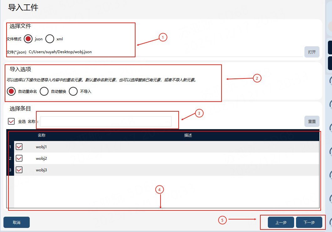
① |
Work object import file |
② |
Work object import option, which is the strategy for handling entry conflict |
③ |
Filter box |
④ |
Work object import entry |
⑤ |
Work object import button |
Import steps: First, select the work object file to be imported in ①, and filter by name in ③, if necessary. Then, select the conflict handling strategy in ② and the work objects to be imported in ④. Finally, click the "Next" button in ⑤ to execute the import, and the selected work objects will be imported locally.