9.6 Calibration of the base frame
The base frame is located at the center of the robot base, described relative to the world frame, and defines the robot’s relative pose to the world frame. In scenarios such as robot inversion, wall installation, and multi-robot collaboration, it is usually necessary to first calibrate the base frame; otherwise, abnormalities such as robot overload, shaking, and force control failure may occur.
There are two methods for calibrating the base frame: manual input and six-point calibration.
9.6.1 Manual input
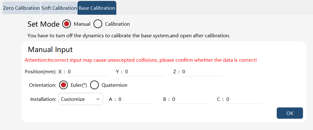
Manually input the position and orientation of the base coordinate relative to the world frame, and the orientation can be selected from Euler angles or Quaternions.
If you choose the two preset installation methods (front and back), the orientation value can be automatically set; if you choose the "Custom" method, it can be manually entered.
9.6.2 Six-point calibration
| Step | Graphical Representation | Explanation |
|---|---|---|
1. Calibrate a tool; |
||
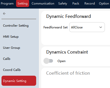
2. If it is not front installation, turn off the dynamics feedforward first (Settings -> Dynamic settings − Dynamic feedforward); |
|
|
3. Select "Calibration" for the calibration mode of the base frame; |
|
|
4. Define the position of auxiliary positions, which is optional; |
|
When the robot’s tool cannot reach the world coordinate system due to excessive distance, the base frame can be calibrated using auxiliary points. The auxiliary position is defined according to the world frame. |
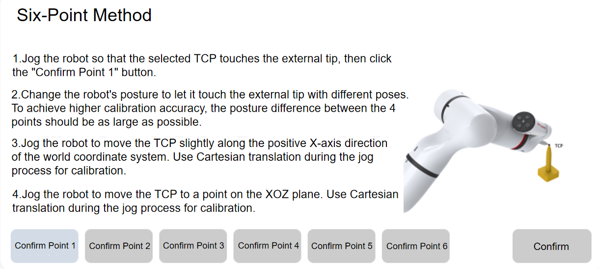
5. Follow the HMI steps to complete the settings for the six points, and click "OK". |
|
|
6. Choose whether to save the base frame data according to the calibration result. |