9.5 Calibration
The xCore system provides robot calibration functions, including mechanical zero calibration, soft calibration (industrial robot), force sensor zero calibration (collaborative robot), and base frame calibration. The calibration function can perform one-key calibration or single-axis calibration.
9.5.1 Zero calibration
The zero calibration here refers to the mechanical zero calibration, which aims to make the theoretical zero of the robot coincide with the actual mechanical zero.
The zero scale is preset on the robot body, and the joints are aligned, that is, after returning to the mechanical zero, the calibration can be performed.
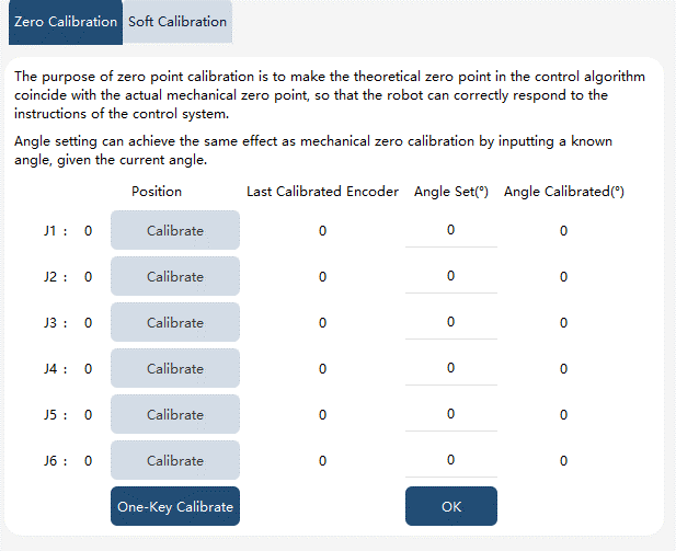
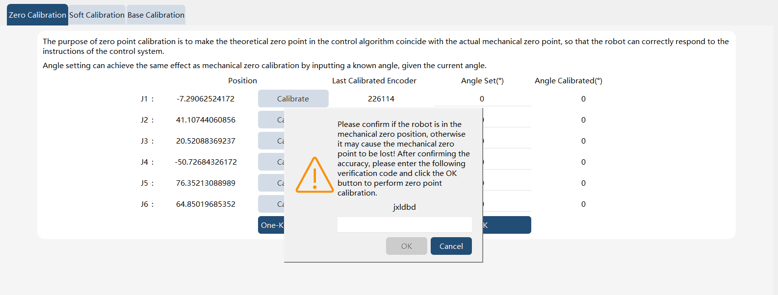
To prevent users from losing the zero due to accidental operation during zero calibration, after clicking the "Calibrate" button for each axis or the "One-Click Calibration" button, a verification code must be entered and "Confirm" clicked to make the calibration operation take effect.
|
Please do not calibrate the mechanical zero arbitrarily, and ensure that all robot joints are at the zero point using the mechanical zero calibration block before calibration. Do not perform the mechanical zero calibration on the robot after it is calibrated by a laser tracker. Otherwise, the zero calibrated by the laser tracker will be lost, therefore affecting the robot accuracy. In case the zero of the robot is lost, please contact ROKAE to restore the zero. |
In some space-constrained scenarios, the robot may not be able to return to the mechanical zero, so the "Angle Calibration" function can be used at this time. The prerequisite for using this function is to know the joint angle of the robot at the calibration time, input it into the "Angle Calibration", and then calibrate it, which can achieve the same effect as calibrating at the zero position.
Example:
Taking the xMate7 Pro robot as an example, assuming there is an obstacle above the 4-axis space, the robot cannot reach the vertical state of the mechanical zero and needs to perform zero point calibration. The robot can be adjusted to the right angle state shown in the following figure through jogging. At this point, the 4-axis is 90 degrees. Then, in the "Angle Calibration", enter the current corresponding angle information (the 4-axis: 90 degrees, and the rest: 0 degrees) to proceed.
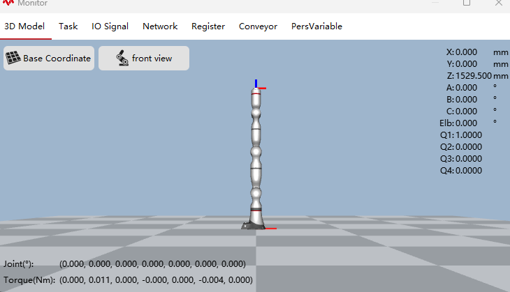
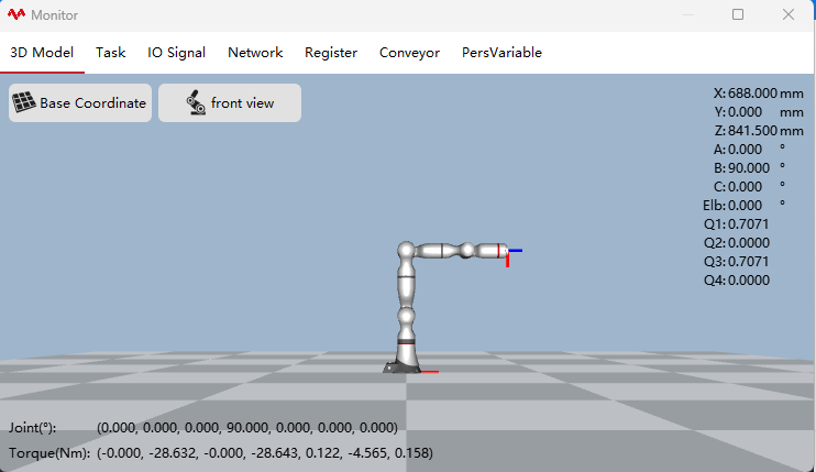
Please note that in the above example, although it is calibrated in a different orientation, the zero of the robot remains in a vertical state. Therefore, if you directly use the  Quick Turn to Zero function after a successful angle calibration by inputting the current angle of the 4-axis at 90 degrees, the robot will still move to the vertical state of the mechanical zero and thus collide with the obstacles! So bear in mind that the Angle Calibration function calibrates the zero. It does not mean that the zero is at the current angle.
9.5.2 Soft calibration
The Soft Calibration function refers to the function of the robot to quickly recover the zero after the zero is lost due to abnormal operations such as encoder battery undervoltage, disassembly of the battery, or accidental touch and removal of multiple loops.
Before using this function, it is necessary to manually jog the robot to the zero (the wide and narrow calibration slots are aligned, and the narrow slots are completely located in the wide slots), and this function cannot restore the zero at any angle.
The Soft Calibration function is supported for both industrial and collaborative robots
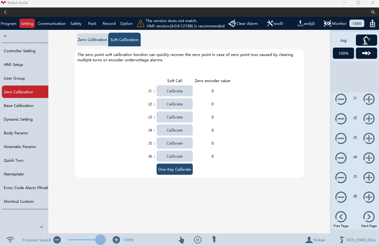
As shown in the figure above, the soft calibration operation steps are as follows:
-
Manually jog the robot to zero (the wide and narrow calibration slots are aligned, and the narrow slots are completely located in the wide slots);
-
Enter the "Main Menu − Settings − Zero Calibration− Soft Calibration" interface;
-
Click the "one-key calibration" button and confirm the pop-up prompt to retrieve the zero, and the zero encoder value displays the encoder value of the zero of each axis;
-
Click the "Calibration" button corresponding to each axis, and confirm the pop-up prompt to retrieve the single-axis zero.
9.5.3 Force sensor calibration
The calibration is aimed at the xMate series of collaborative robots. During the long-term use of the robot, the torque sensor may inevitably produce zero drift, which is manifested as the robot dragging and drifting.
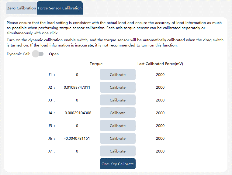
After a similar problem occurs, the robot can be adjusted to the zero position to perform single-axis calibration or one-key calibration.
If you want to calibrate the force sensor at any position, you can turn on the "Dynamic calibration" switch, and then perform single-axis calibration or one-key calibration. The calibration accuracy of this method may not be as good as that of performing force sensor calibration at the zero position of the robot. In addition, after the dynamic calibration function is turned on, when the force control is turned on in the drag and RL program, the system will automatically zero to ensure the normal use of force control related functions.
|
Dynamic calibration involves two risks:
For these reasons, dynamic calibration should not be turned on unless the torque sensor zero sees serious drifting. This function switch defaults to the off state. |
9.5.4 20-point calibration
When the robot’s zero position is lost or shifted, its accuracy degrades and fails to meet on-site accuracy requirements. This function is used to calibrate the zero position and improve the robot’s accuracy.
This function is available for only 6-axis robots (including both industrial and collaborative robots) and is not compatible with external axes or tracks. External axes or tracks, if any, must be disabled.
9.5.4.1 Function interface
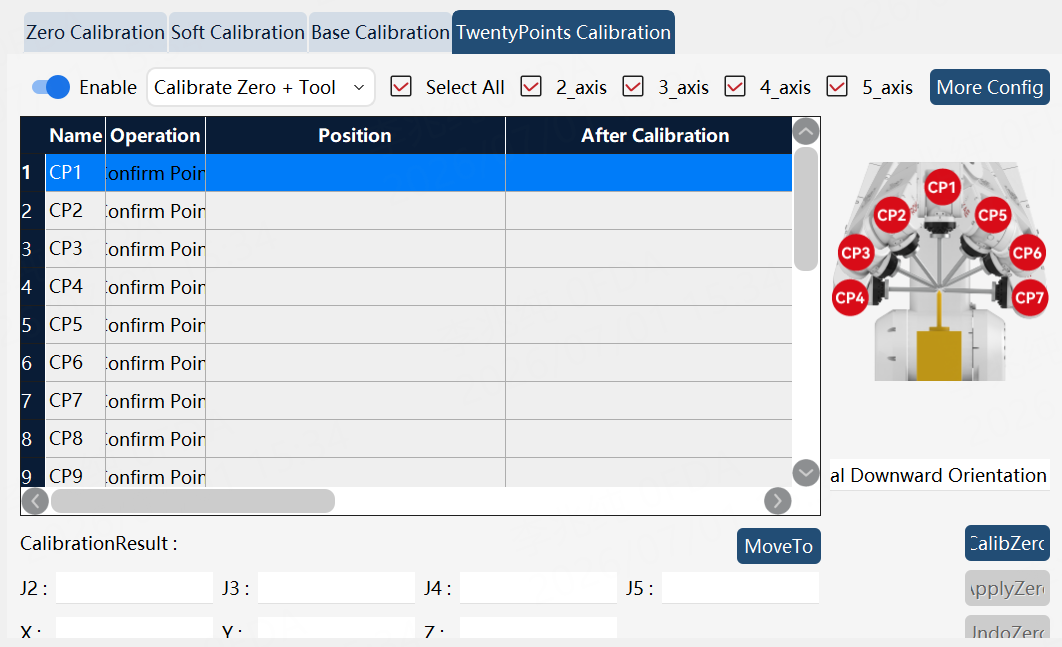
The function interface for the 20-point calibration is shown in the figure below. The top section is the function switch and parameter setting area. Users can set parameters such as the calibration method and axes. The convergence error threshold and the minimum orientation spacing can be set by clicking the "More settings" button.
The middle section is the point guidance and calibration area. On the left is the list of calibration points, and on the right is the calibration point illustration and description area. When you click a point in the calibration point list, the right side will show the orientation illustration and suggested orientation description for that point.
The bottom section is the calibration result display and function button area. Before calibrating the zero, the calibration result remains null. After clicking the "Calibrate zero" button and completing calibration, the text box on the left will show the calibration results for each axis. At this point, you can click the "Undo zero" button to clear the current calibration results. Alternatively, you can click the "Apply zero" button to update the robot’s zero position, which is valid only after a controller restart.
9.5.4.2 Preparation
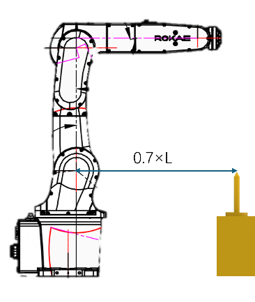
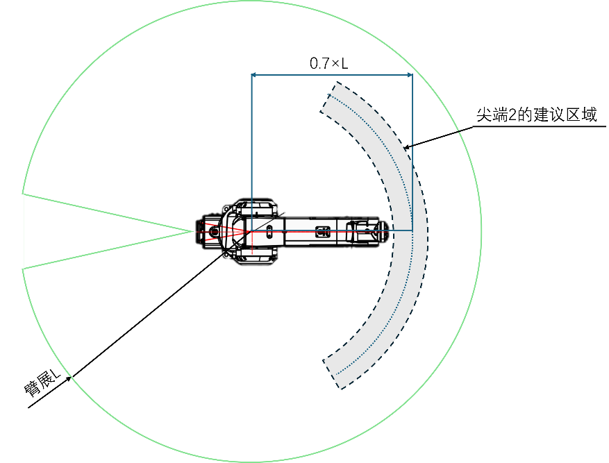
This function requires two fixtures equipped with tips. Tip 1 is mounted on the robot flange, and Tip 2 is fixed at a point within the robot’s working space. Assuming the robot’s reach is L, it is recommended to position Tip 2 according to the following guidelines:
-
The distance from the fixed point to the robot’s base frame shall be approximately 0.7L.
-
The apex of Tip 2 shall be roughly at the same height as the robot’s second-axis joint.
|
|
9.5.4.3 Parameter setting
-
Enable switch:
To activate this function, the following conditions must be met:
-
The user must be logged in with "system."
-
The tool parameter setting in the upper right must be one of the global tool parameters (g_tool_0 to g_tool_15).
-
The tool parameter must correspond to a handheld tool that has been calibrated.
-
The work object parameter setting in the upper right must be wobj0.
-
Calibration method:
-
-
Zero calibration + tool dimensions: Calibrate both the zero and the tool parameters simultaneously.
-
Zero calibration only: Calibrate the zero only without updating the tool parameters. Compared to Method 1, this procedure provides higher accuracy in zero calibration.
|
How to choose the calibration method? If the robot has not lost its zero and a global tool parameter (g_tool_x) has previously been calibrated, set g_tool_x as the current tool parameter and select the calibration method “Zero calibration only.” Otherwise, select the calibration method “Zero calibration + tool dimensions.” |
-
Calibration axes:
This function is used only to calibrate the zero positions of axes 2, 3, 4, and 5. Any combination of these axes (2–5) can be selected for calibration.
If you can identify which axis has lost its zero, it is recommended to select only this axis for zero calibration. If you are unsure which axis has lost its zero, it is recommended to select all axes for zero calibration.
-
More settings:
The following two parameters can be set here:
-
Convergence error threshold (in mm): It refers to the possible error between the Tip 1 mounted on the flange and the externally fixed Tip 2, even when they appear visually aligned to the human eye. Modification of this parameter is not recommended.
-
Minimum orientation spacing (in °): It defines the angle between the orientations of any two calibration points. If any two points of the 20 calibration points have an orientation angle smaller than this value, zero calibration will fail. Modification of this parameter is not recommended.
9.5.4.4 Point calibration
This function requires manually controlling the robot to bring Tip 1 into contact with Tip 2 using 20 different orientations. The orientations for CP1 to CP20 are described in the table below.
Calibration point |
Point orientation illustration |
Point orientation description |
CP1 |
|
Vertically downward |
CP2 |
|
Based on Point 1, jog A+ by 30°. |
CP3 |
|
Based on Point 1, jog A+ by 60°. |
CP4 |
|
Based on Point 1, jog A+ by 90°. |
CP5 |
|
Based on Point 1, jog A- by 30°. |
CP6 |
|
Based on Point 1, jog A- by 60°. |
CP7 |
|
Based on Point 1, jog A- by 90°. |
CP8 |
|
Based on Point 1, jog B+ by 15°. |
CP9 |
|
Based on Point 1, jog B+ by 30°. |
CP10 |
|
Based on Point 1, jog B+ by 45°. |
CP11 |
|
Based on Point 1, jog B- by 20°. |
CP12 |
|
Based on Point 1, jog B- by 40°. |
CP13 |
|
Based on Point 12, jog C+, 20°. |
CP14 |
|
Based on Point 12, jog C+, 40°. |
CP15 |
|
Based on Point 12, jog C+, 60°. |
CP16 |
|
Based on Point 12, jog C+, 90°. |
CP17 |
|
Based on Point 12, jog C-, 20°. |
CP18 |
|
Based on Point 12, jog C-, 40°. |
CP19 |
|
Based on Point 12, jog C-, 60°. |
CP20 |
|
Based on Point 12, jog C-, 90°. |
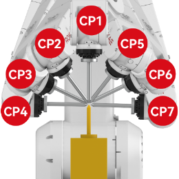
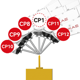
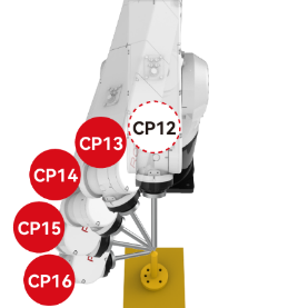
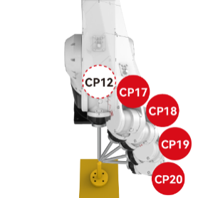
When you click any point in the calibration point list, the right side will show the orientation illustration and suggested orientation description for that point in the guidance area. It is recommended to calibrate the 20 points sequentially by the following steps:
-
Select a line in the calibration point list, and jog the robot into the target orientation according to the orientation illustration and description on the right.
-
Fine-tune the Cartesian position to precisely align the apexes of Tip 1 and Tip 2.
-
Click the "Confirm point" button to complete the point calibration.
-
Jog the Z-axis upward to lift Tip 1 slightly, preventing potential collisions between the two tips when moving to the next calibration point.
|
In practical applications, certain orientations may be unreachable. In such cases, you can redistribute the angles of calibration points. For example, during the calibration of CP4, if it’s impossible to jog the A+ by 90° based on CP1 because the maximum achievable angle is only 70°, you can redistribute the angles of CP2, CP3, and CP4 based on CP1. The orientations of CP2, CP3, and CP4 can be adjusted according to the table below. Similar adjustments can be made whenever other calibration points are unreachable. |
Calibration point |
Description of point orientations after adjustment |
CP2 |
Based on Point 1, jog A+ by 25°. |
CP3 |
Based on Point 1, jog A+ by 50°. |
CP4 |
Based on Point 1, jog A+ by 70°. |
|
The following five issues may lead to significant errors in the calibration results:
|
9.5.4.5 Application of calibration results
After all 20 points are successfully calibrated, the zero position can be calibrated by clicking the "Calibrate zero" button. Then, one of the following results may produce:
Calibration result |
Cause |
Phenomenon |
Optional operation |
Success |
Show calibration results |
Apply zero |
|
Success, with singularities |
During calibration of one or more points, the tips are not properly aligned. |
Show calibration results, with the names of the relevant points highlighted in red. |
1. Apply the zero. 2. Undo the zero, fine-tune the relevant points, and then recalibrate the zero. |
Fail |
During calibration of more than eight points, the tips are not properly aligned./The orientations of two points are similar. |
Do not show calibration results, with the names of the relevant points highlighted in red. |
After recalibrating the relevant points, perform the zero calibration again. |
If the calibration is successful, the following interface will appear.
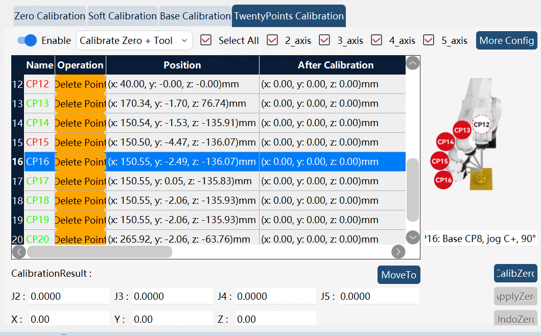
The calibration result bar in the bottom left displays the zero positions of axes and the position components of corrected tool parameters. In the calibration point list, the “After correction” column shows the TCP positions of calibration points after zero calibration. The accuracy of the zero calibration can be evaluated based on the deviations among these corrected TCP positions.
At this time, you can click the "Apply zero" button, which will automatically set the calibrated results as the zero positions. If the selected calibration method is “Zero calibration + tool dimensions, ” the corresponding tool parameters will also be modified accordingly, and the controller will automatically restart.
9.5.4.6 Others
Performing the 20-point calibration while full DH compensation is enabled does not affect the zero positions when the full DH compensation is disabled.
Performing the 20-point calibration while full DH compensation is disabled does not affect the zero positions when the full DH compensation is enabled.