9.10.1 Basic motion parameters
Motion parameters include the maximum speed, the maximum acceleration, and the maximum jerk of each axis of the robot, which affect the motion rhythm and ride of the robot. The robot has a set of default parameters before leaving the factory. Modifying the above parameters may cause the robot to shake abnormally, report errors, and affect the service life of the robot. Please modify it carefully.
1 |
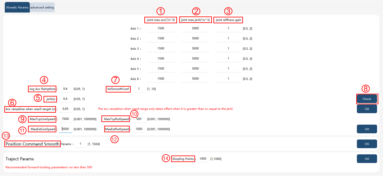
Joint max acc: The upper limit of acceleration for each axis of the robot, which is limited by the torque capacity of the motor. When the dynamic constraint is turned off, this parameter takes effect; when the dynamic constraint is turned on, this parameter fails. This value is generally not less than 3−5 times the maximum axis speed. When setting the maximum axis acceleration via command, the dynamic constraint switch must be enabled. |
2 |
Joint max jerk: The upper limit of the jerk of each axis of the robot. Under normal circumstances, with the increase of jerk, the rhythm of the robot will increase to make it easily shake when moving. If there are many small turning zones in the robot’s motion, it is possible to increase the jerk appropriately to increase the rhythm, but attention should be paid to the robot’s shake. This value shall not less than 3−5 times the maximum axis acceleration. |
3 |
Joint flexibility coefficient: A coefficient for adjusting the stiffness model of robot joints, with a configurable range of . Modifying this coefficient will affect both gravity compensation and vibration suppression performance. Note: This value generally does not need to be adjusted, and the default value is enough. In special circumstances, please modify it under the guidance of the manufacturer. |
4 |
Jog acc ramptime: The time it takes for the robot’s acceleration to increase from minimum to maximum during Jog, which only takes effect in 10 mm step Jog and continuous mode Jog. The smaller the value, the faster the robot Jog starts and stops, but the more prone to shake. If the robot reacts slowly when Jog is felt, the value can be adjusted appropriately. |
5 |
Acceleration rise time: The time it takes for the robot to increase its acceleration from a minimum to a maximum during motion program execution. The smaller the value, the faster the robot accelerates, and vice versa. |
6 |
Deceleration rise time during final stop phase: For target points without a turning zone, this is the time it takes for the robot’s deceleration to increase from its minimum value to 0 during the final stop phase. The longer the deceleration rise time, the more gradual and smooth the robot’s stopping will be. If the acceleration rise time is greater than the deceleration rise time during the final stop phase, the robot will use the longer acceleration rise time for stopping. |
7 |
VelSmoothCoef: It is used to adjust the speed smoothing process when the robot passes through the turning zone. The larger the value, the smaller the speed deceleration when the robot passes through the turning zone, and the easier it is to shake. When the value is set to 1.0, the velocity is not smoothened when the robot passes through the turning zone. This parameter is mainly used to improve the extreme performance of the robot. When debugging, first confirm the shake of the robot when the value is 1.0: if the robot shakes violently, it indicates that the robot has reached its extreme performance, and this parameter does not need to be increased; if the robot runs smoothly but experiences severe deceleration when passing through turning zones, gradually increasing this parameter can improve motion smoothness. When debugging this parameter, it is recommended to gradually increase it in steps of 0.1−0.5. |
8 |
Check: After clicking, the current motion coefficient parameters and system default motion coefficient parameters will be displayed; |
9 |
Maximum TCP linear velocity: Set the vmax parameter for TCP linear speed |
10 |
Maximum TCP rotation velocity: Set the vmax parameter for TCP rotation speed |
11 |
Maximum external axis linear velocity: Set the vmax parameter for external axis linear velocity |
12 |
Maximum external axis rotation velocity: Set the vmax parameter for external axis rotation velocity |
13 |
Position command smoothing parameter: Configure the smoothing level applied by the controller to the robot’s joint position commands, with an adjustable parameter range of . When the value is set to 1, the controller applies no smoothing to the joint position commands. As the value increases, the smoothing level increases, resulting in smoother and slower robot motion. Modifying the position smoothing parameter affects both the robot’s cycle time and position accuracy. Note: This value generally does not need to be adjusted, and the default value is enough. In special circumstances, please modify it under the guidance of the manufacturer. Robots using the ARM platform do not support position command smoothing parameter setting. |
14 |
Sampling points: The larger the value, the smoother and faster the robot motion, but it will affect the timeliness of logic and signal processing. Note that this value generally does not need to be adjusted, the default value is enough. In special circumstances, please modify it under the guidance of the manufacturer. |
9.10.2 Advanced settings
9.10.2.1 Safety control
It supports several stop modes, and the stop parameters of each can be set;
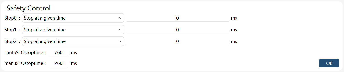
Currently, the deceleration to a complete stop at maximum capability is being used. After receiving the stop signal, ensure that the robot path is not offset and at least one motor is planned to stop according to the maximum deceleration capacity.
Considering that the actual performance of different robots can be easily influenced by various factors under different working conditions, this stopping method permits the configuration of a scaling factor, which can be set within the range of . When it is set to the maximum value of 1, the robot quickly reaches the motor’s maximum capability for deceleration and stopping. When it is set to the minimum value of 0.1, the robot gradually approaches the motor’s maximum capability, resulting in a smoother deceleration and stop. The larger the scaling factor, the more quickly the robot reaches the motor’s maximum torque value, resulting in a more rapid stop. Conversely, the smaller the scaling factor, the more gradually the robot approaches the motor’s maximum torque value, leading to a smoother and more gradual stop.
Additionally, the stop coefficient for manual mode (Stop 0) and the stop coefficient for automatic mode (Stop 1) can be set independently.
9.10.2.2 Search command max stop distance
When a Search command is used and the stop mode is selected for a quick stop, the distance traveled by the robot TCP from the receipt of the stop signal to the full stop of the robot shall not exceed this value.

9.10.2.3 Minimum turning zone radius
The minimum turning zone radius setting defines the shortest permissible turning zone size that can be generated. This parameter can be used to avoid generating a turning zone too short and to make motion smoother. When the control system detects that the length of a trajectory is below the set value of this parameter and the trajectory needs to generate a turning zone, the control system will automatically combine the trajectory and the adjacent trajectories into one trajectory and generate a turning zone with an appropriate length. The larger the value, the longer the minimum turning zone and the smoother the robot passes through the turning zone. When this parameter is set to 0, the control system strictly follows the parameters to generate the turning zone.

9.10.2.4 Stacking debug mode
The stacking debug mode option will only be displayed and available when the model type is CR, SR, and Industrial Six-Axis Robot (NB, XB) series models. When this mode is turned on, two Jog frames corresponding to four-axis locking are added: singularity avoidance and parallel base.
Note: CR series 5-axis models turn on this mode by default. At this time, Jog under the base frame corresponds to the singularity avoidance frame of the 6-axis model.
9.10.2.5 Default Conf
The "RL" option in Defualt Conf is used to set whether motion commands strictly adhere to the movement constraints defined by the Conf information for each point after reloading an RL project. Note: After modifying this option, you need to run PPTOMAIN to apply the changes and make the option effective.
The "Point Move to" option in Default Conf is used to set whether motion commands strictly adhere to the movement constraints defined by the Conf information for each point when performing "Point Move to" operations.
Note: By default, all the 4 buttons in the Default Conf are enabled until modifications are made in this interface.
