9.12 Quick adjustment
Users can define multiple commonly used positions. By using buttons or commands, the robot can quickly adjust its position and orientation (pose). It supports custom poses including the drag pose, transport pose, and Home pose. The above poses have default values for specific models, and also support user customization.
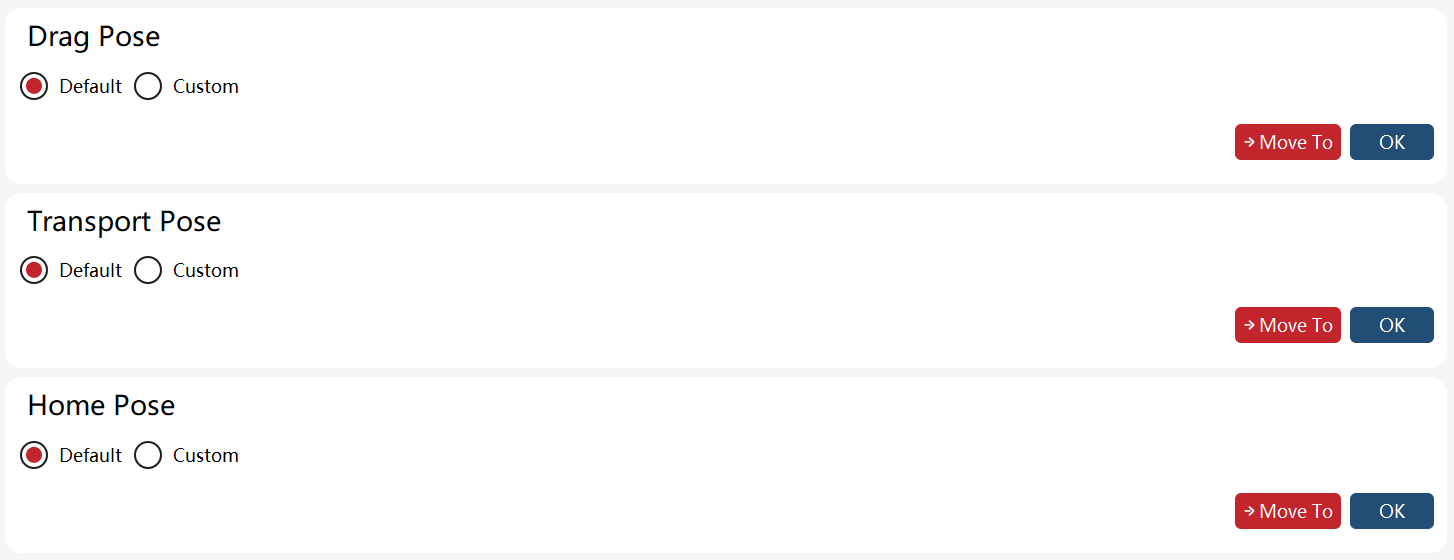
The Home pose is quite unique, in addition to defining the reference position, it also requires setting a set of offsets. When the difference between the robot’s current position and the reference position is less than the specified offset, the robot is considered to be in the Home pose. In this case, the system I/O signal "Home State" and the function code register "sta_home" will generate corresponding outputs.
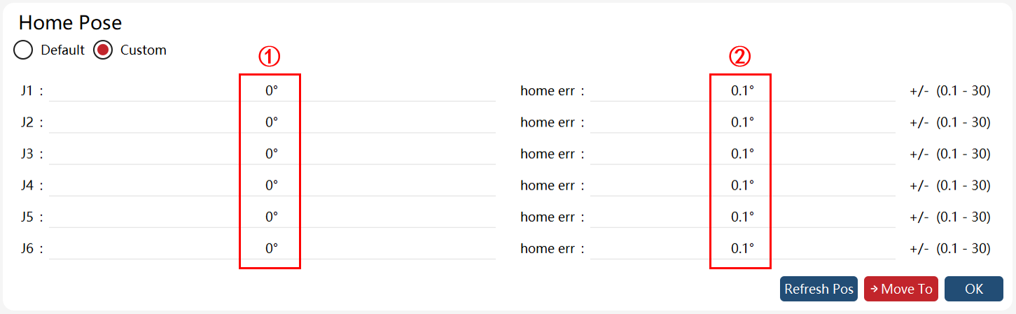
S/N |
Name |
Meaning |
① |
Reference Value |
The reference value of origin for each joint. |
② |
Offset |
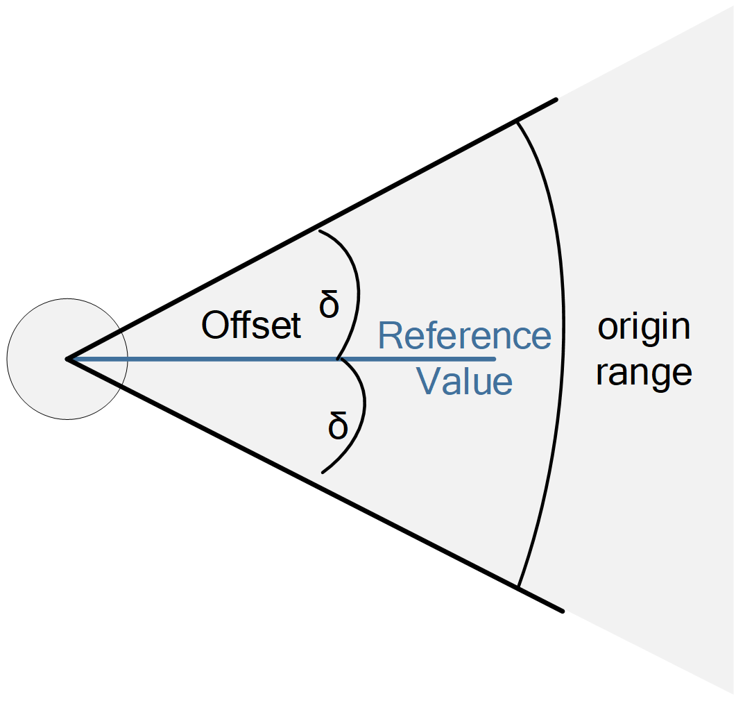
The float value of the origin range symmetrically around the reference value. Offset value range: . For example, if the reference value is 1° and the offset value is 3°, the origin falls in the range of . |
The relationship between the origin range, the reference value, and the offset value is shown as follows:

This quick adjustment function also allows rapid adjustment of the end-effector to specified orientations while maintaining the robot’s TCP position and arm angle (the concept of arm angle applies only to 7-axis robots). The tool quick adjustment offers two configurable options: "Frame selection" and "Adjustment method".
The Frame selection dropdown includes:
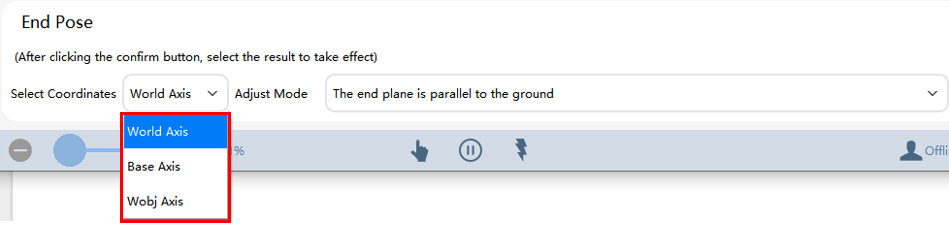
The Adjustment method dropdown includes: (When a frame is selected in the "Frame selection", the contents of the "Adjustment method" dropdown will change accordingly. The example below shows the available options of the "Adjustment method" when the world frame is selected in the "Frame selection")
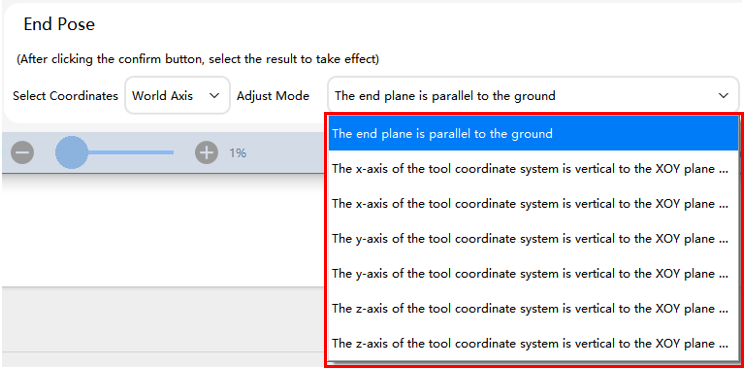
Procedure:
The usage of the quick adjustment function is similar to JOG operation. The specific steps are as follows:
-
Ensure that the correct tool and work object are selected;
-
Determine the target pose of the robot’s end-effector;
① Select the frame: (For example, select the world frame as shown in the figure below)
② Select the adjustment method: (For example, Align the flange plane parallel to the ground, as shown in the figure below)
③ Click "Confirm" to apply;

-
Switch to manual mode and power on;

-
Press and hold the "Move to" button. The robot will move to the target pose via joint-space trajectory;

Note:
-
When using the quick adjustment function to adjust the pose, please turn on the soft limit to avoid unexpected collisions.
-
The motion speed can be adjusted via the Jog speed. If the power is turned off or the "Move to" button is released during motion, the robot will stop moving.
-
Use matched tool/work object types (hand-held tool/external work object or hand-held work object/external tool). Otherwise, motion will be prohibited, and corresponding error prompts will be displayed for incorrect selection;
-
In the case of an external tool, adjustments perpendicular to the XOY plane of either the world or base frame are not allowed, and incorrect selections will trigger corresponding error prompts.