9.7.1 Global tool list
9.7.1.1 Overview
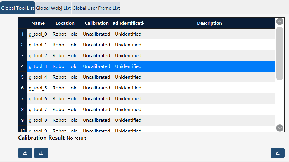
Global tool definition is consistent with tool definition. In the xCore control system, the data type corresponding to global tools is "g_tool_num", with the num ranging from 0 to 15, totaling 16 global tools. Global tools also belong to the tool type. For detailed descriptions of tools, please refer to the "RL commands - Variables" section. Note that global tools differ from tools within individual projects; global tools can be used across all projects.
9.7.1.3 Operation example - creating a global handheld tool
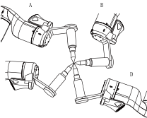
Before the calibration of tool frame, the user needs to prepare a fixed external point, which shall be located within the robot’s working range and can be contacted by the calibrated tool in a very flexible orientation.
Operation |
Graphical Representation |
Explanation |
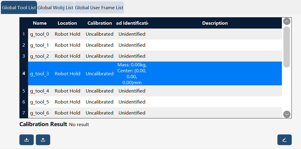
1. In the Frame calibration - Global tool list interface, select the global tool to be edited. |
|
When logged in with "Programmer" or higher permissions, editing operations can be performed on the selected global tool. However, only editing is allowed; new tools cannot be added, nor can existing tools be deleted. |
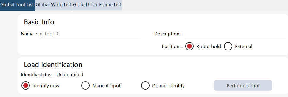
2. Set the tool attribute: Robot hold. |
|
|
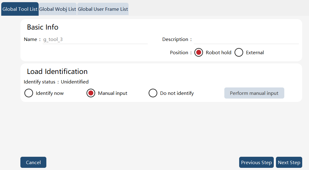
3. Load identification (taking manual input as an example): Select "Manual Input, " click the "Perform manual input" button, and enter the "Tool Load Identification" page. |
|
Input the physical information of the tool, click the "Next Step" button, and return to the "New Tool" page. At this point, the "Identify status" will be displayed as "Identified". |
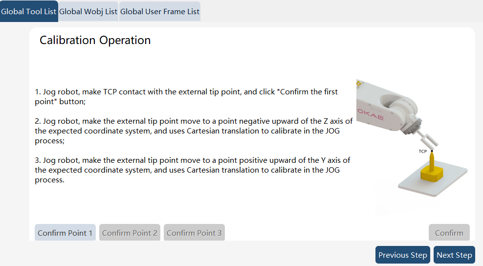
4. Pose calibration, taking the three-point method as an example: Select "Calibrate now" and set the calibration method to "3 Points". Then, click the "Perform calib" button to enter the "New User Frame" page to perform the calibration. |
|
Jog the robot to move the calibrated tool TCP to the points of the desired frame in sequence: the origin, a point on the x-axis, and a point on the xy-plane or on the y-axis, and click the "Confirm Point 1", "Confirm Point 2", and "Confirm Point 3" buttons accordingly. After confirming all three points, click the "Confirm" button to return to the "New Tool" page, where the "Calibration Status" will now be displayed as "Calibrated." When the four-point method is used to calibrate the tool origin, the orientation differences between the four points shall be as large as possible. In other words, the robot shall try to contact the external point in different orientations. |
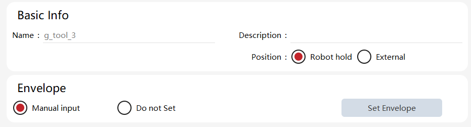
5. Envelope: Select "Manual Input", click "Execute Envelope Editing", and enter the "Envelope Settings" interface to choose the envelope. |
|
|
6. Click the "Complete" button to finish editing the global tool. |
|
The newly created tool will be displayed in the global tool list. |
9.7.1.4 Operation example - creating a global external tool
The calibration methods for global external tools are consistent with those for global handheld tools, supporting three methods: six-point method, four-point method, and three-point method.
Attention: To calibrate the external tool frame, it is necessary to use the already calibrated handheld tool.
Operation |
Graphical Representation |
Explanation |
1. If a calibrated handheld tool already exists in the list, it can be used to assist in the calibration of an external tool. In this example, we will use "g_tool_0" as the reference. |
|
The external tool to be calibrated shall have a tip. |
2. Click the "Edit" button in the lower-right corner of the Global Tool List interface to enter the Global Tool wizard interface. |
|
Users with the permission level of "Programmer" or above can perform edit operations. |
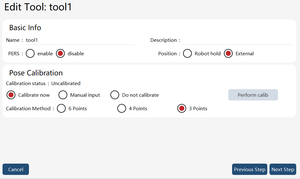
3. Set the tool attribute: External. |
|
|
4. Switch between tools in the upper right corner and select the already calibrated handheld tool, "g_tool_0". |
|
|
5. Pose calibration, taking the four-point method as an example: Select "Calibrate now" and set the calibration method to "4 Points". Then, click the "Perform calib" button to enter the "Tool Calibration" page to perform the calibration. |
|
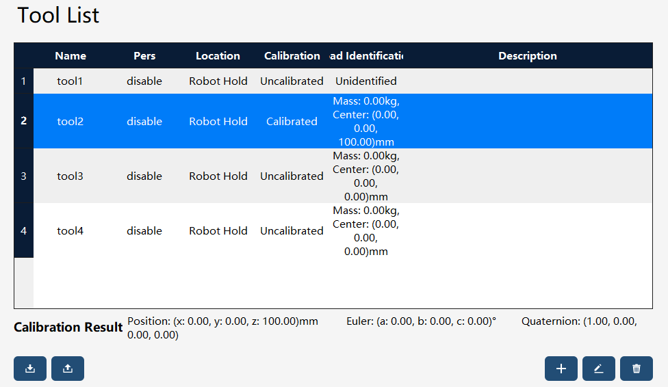
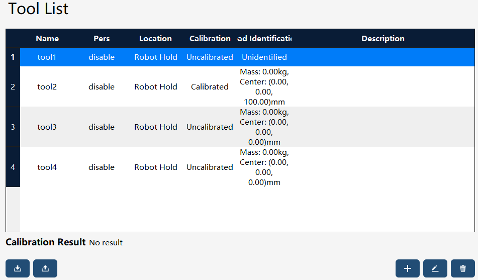
Jog the robot so that the TCP of the calibrated tool can point at the origin of the desired work object frame in different orientations, and then confirm the first, second, third, and fourth points respectively. The orientation difference between the 4 points shall be as large as possible, which means the robot shall try to contact the external point in different orientations. After the calibration is completed, the system will pop up the calibration error. Select whether to re-calibrate according to the error situation (refer to the confirmed calibration accuracy). |

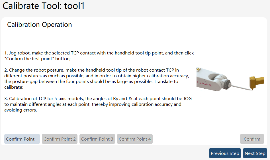
Note:
The external tool must be used together with the corresponding work object, meaning among the Position parameters which are selected at the same time in the tool and work object respectively, one must be External while the other be Robot hold. Otherwise, the system will prompt an error and forbid jogging the robot.
The reference frames for defining tool frames and work frames of external tools differ from those for defining tool frames and work frames of normal tools. You can refer to the following table.
Frame name |
Definition of a normal tool relative to … |
Definition of an external tool relative to … |
Work object frame |
User frame |
User frame |
User frame |
World frame |
Flange frame |
Tool frame |
Flange frame |
World frame |
9.7.2 Global work object list
9.7.2.1 Overview
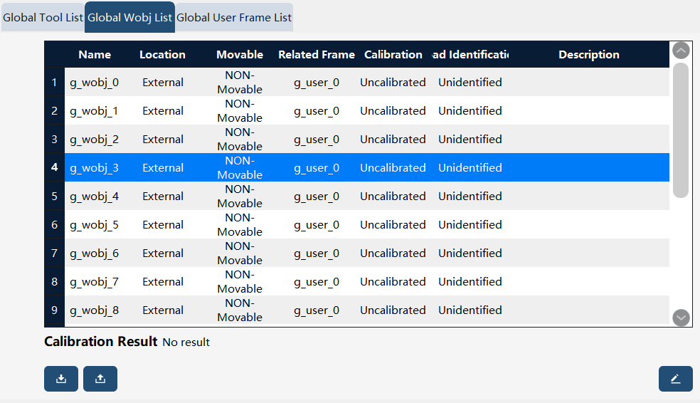
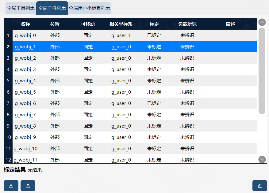
Global work object definition is consistent with work object definition; see 8.13.1 for details. In the xCore control system, the data type corresponding to global work objects is "g_wobj_num", with the num ranging from 0 to 15, totaling 16 global work objects. Global work objects also belong to the work object type. For detailed descriptions of work object, please refer to the "RL commands - Variables" section. Note that global work objects differ from work objects within individual projects; global work objects can be used across all projects.
9.7.2.2 Operation example - creating a global external work object
To calibrate the global external work object frame, it is necessary to use an already calibrated handheld tool for assistance.
Operation |
Graphical Representation |
Explanation |
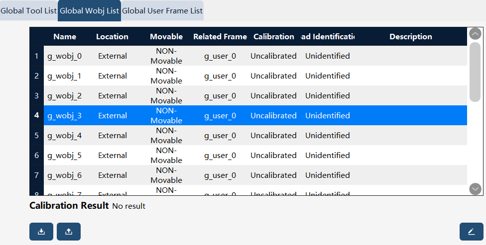
1. Click the "Edit" button in the lower-right corner of the Work Object List interface to enter the Global Work Object Edit wizard interface. |
|
Users with the permission level of "Programmer" or above can perform edit operations |
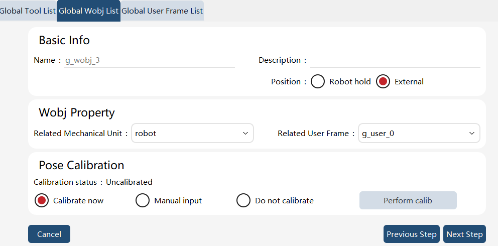
2. Set the global work object attribute: external. |
|
|
3. Switch the tool in the upper right corner to the already calibrated global handheld tool, "g_tool_0" |
|
|
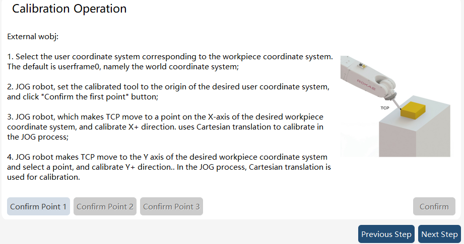
4. Click the "Execute Calibration" button to enter the global work object calibration interface. |
|
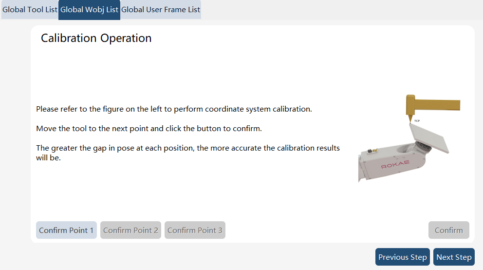
Jog the robot to point the calibrated tool TCP to the desired origin of the work object frame, and click the "Confirm Point 1" button. Then, Jog the robot to point the TCP to a point on the desired X-axis of the work object frame, and click the "Confirm Point 2" button. After that, Jog the robot to point the TCP to a point on the desired Y-axis of the work object frame, and click the "Confirm Point 3" button. Finally, click "Confirm Calibration" to bring up a dialog box for confirming the calibration results, and click "Confirm." Then, Click the "Complete" button to return to the "Global Work Object List Editing" page. |
5. Click the "Complete" button to finish editing the global work object. |
|
The successfully edited global work object will be displayed in the Global Work Object List. |

9.7.2.3 Operation example - creating a global handheld work object
To calibrate the global handheld work object frame, it is necessary to use an already calibrated global external tool for assistance.
Operation |
Graphical Representation |
Explanation |
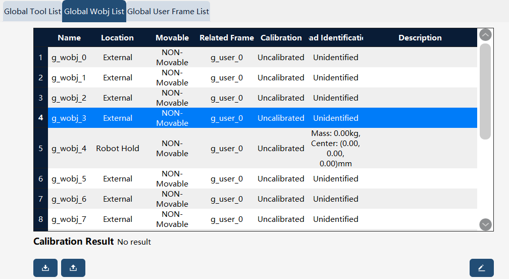
1. Click "Edit" in the bottom right corner of the Work Object List interface to enter the New Work Object wizard interface. |
|
Users with the permission level of "Programmer" or above can perform edit operations. |
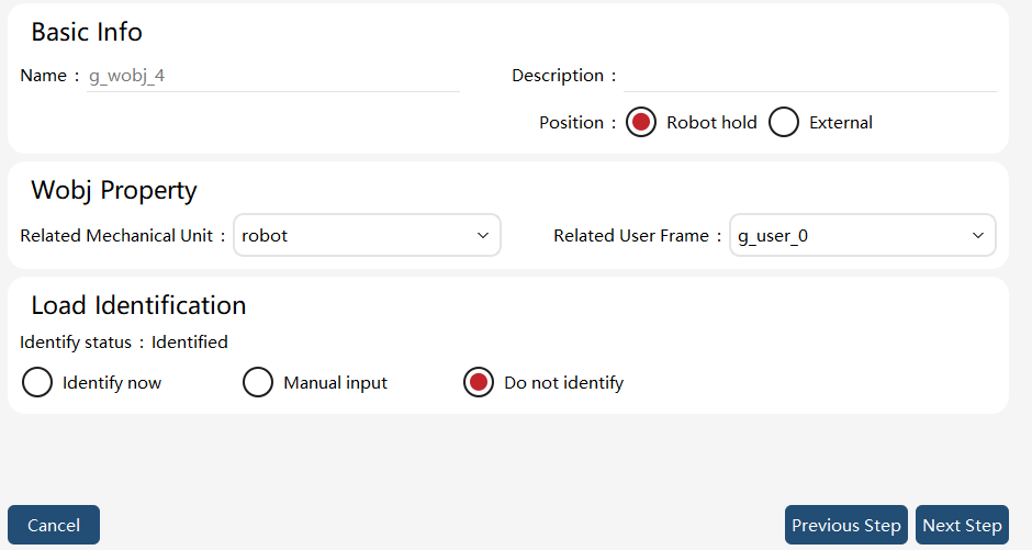
2. Set the work object attribute: handheld |
|
"External" refers to the case where the work object is not fixed relative to the end-effector of the robot, while "handheld" means the case where the work object is fixed relative to the end-effector of the robot. |
3. Switch the tool in the upper right corner to the already calibrated external tool, "g_tool_1" |
|
|
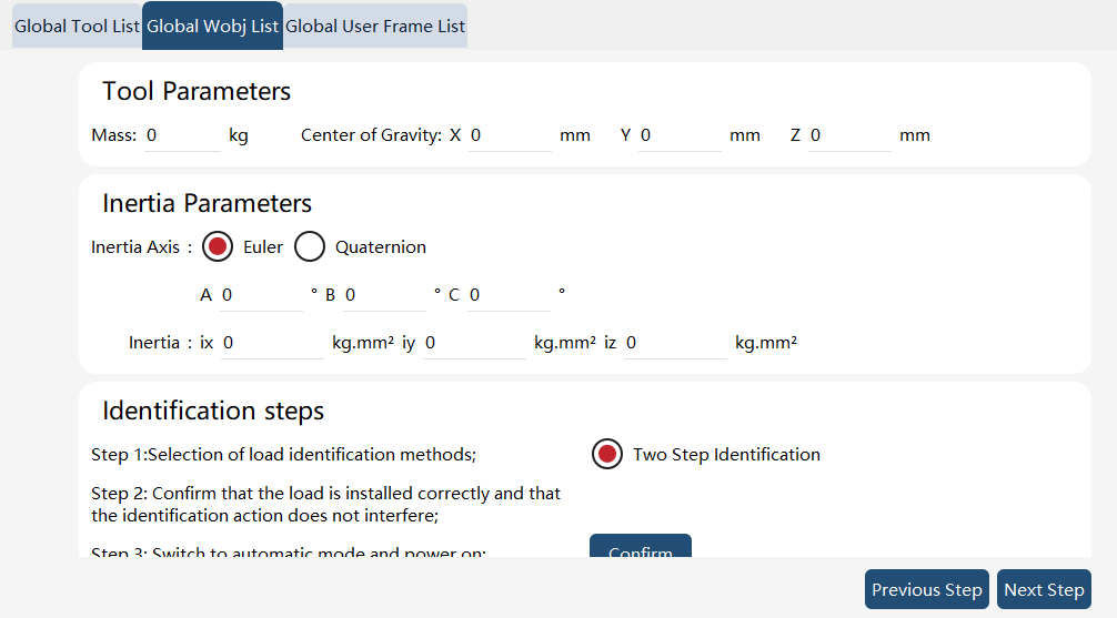
4. Click "Execute Load Identification" to enter the Load Identification interface. |
|
|
5. Click the "Execute Calibration" button to enter the work object calibration interface. |
|
Jog the robot to point the calibrated tool TCP to the desired origin of the work object frame, and click the "Confirm Point 1" button. Then, Jog the robot to point the TCP to a point on the desired X-axis of the work object frame, and click the "Confirm Point 2" button. After that, Jog the robot to point the TCP to a point on the desired Y-axis/XOY-plane of the work object frame, and click the "Confirm Point 3" button. Finally, click "Confirm Calibration" to bring up a dialog box for confirming the calibration results, and click "Confirm." Then, Click the "Next" button to return to the "New Work Object" page |
6. Click the "Complete" button to finish editing the global work object |
|
9.7.3 Global user frame list
9.7.3.1 Overview
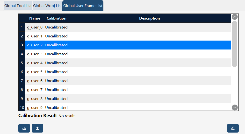
The global user frame serves as a reference frame when defining the work object frame or global work object frame and is not used independently.
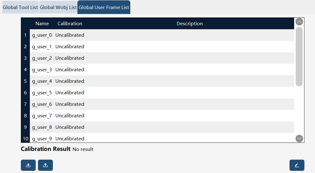
When establishing a global user frame, you can choose "Calibration now", "Manual input" or "Do not calibrate".
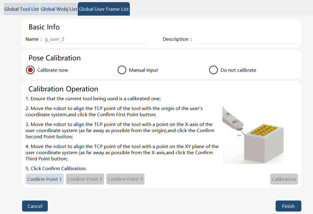
When "Calibration now" is selected, the 3-point method is used to calibrate. Before calibrating the global user frame, the user needs to first calibrate a tool and then use the TCP of the tool to calibrate the user frame. For this, it is recommended to use a tool with tips.
"Manual input" is allowed if the global user frame is known in advance. Another option is "Do not calibrate", in which case the global user frame is considered as the world frame by default.
9.7.3.2 Operation examples
Operation |
Graphical Representation |
Explanation |
1. Click the "Edit" button in the lower-right corner to edit a global user frame. |
|
Users with the permission level of "Programmer" or above can perform edit operations. |
2. Follow the steps shown in the figure to perform the calibration. |
|
Jog the robot to guide the calibrated tool TCP to sequentially point to the desired frame’s origin, a point on the x-axis, and a point on the xy-plane or on the y-axis. Click the "Confirm Point 1", "Confirm Point 2", and "Confirm Point 3" buttons accordingly. After successfully confirming all three points, click the "Calibration" button. |