运动指令
15.4.2 Motion commands
15.4.2.1 MoveAbsJ
Explanation |
MoveAbsJ (Move Absolute Joint) is used to move the robot and the external axis to a position defined by the angle of the axis for rapid positioning or moving the robot to a precise axis angle. All axes move synchronously and the end-effector of the robot moves along an irregular curve. Please be aware of the risk of collision. The tool parameter used in the MoveAbsJ instruction would not affect the end position of the robot, but the tool parameters are still being used by the controller for dynamics calculations. |
Definition |
MoveAbsJ (ToJointPos, Speed, Zone, Tool, ); TojointPos, To Joint Position, data type: jointtarget, the target angle and position value of the robot and the external axis. Speed, Move Speed, data type: speed, to specify the motion speed of the robot when it executes MoveAbsJ, including the translation speed of the robot end-effector, the rotation speed, and the motion speed of the external axis. Zone, Turning Zone, data type: zone, to define the size of the turning zone for the current trajectory. Tool, data type: tool, the tool used when executing the trajectory. The command MoveAbsJ calculates the motion speed and the size of the turning zone using the tool’s TCP data. [Wobj], Work Object, data type: wobj, the work object used when executing this trajectory. When the tool is installed on the robot, this parameter can be ignored; when using external tools, this parameter must be specified, and the robot will calculate the motion speed and the size of the turning zone by using the data saved in wobj. |
Example |
Example 1 MoveAbsJ (j10, v500, fine, tool1); Example 2 MoveAbsJ (startpoint, v1000, z100, gripper, phone); |
15.4.2.2 MoveJ
Explanation |
MoveJ (Move The Robot By Joint Motion) is used to move the robot from one point to another when the motion trajectory of the robot end-effector is not required. All axes move synchronously and the end-effector of the robot moves along an irregular curve. Please be aware of the risk of collision. |
Example |
MoveJ (ToPoint, Speed, Zone, Tool, ); The parameter in is optional and can be omitted. ToPoint, target pose, data type: robtarget, the target position described in the Cartesian space. Speed, Move Speed, data type: speed, to specify the motion speed of the robot when it executes MoveJ, including the translation speed of the robot end-effector, the rotation speed, and the motion speed of the external axis. Zone, Turning Zone, data type: zone, to define the size of the turning zone for the current trajectory. Tool, data type: tool, the tool used when executing the trajectory. The command MoveJ calculates the motion speed and the size of the turning zone using the tool’s TCP data. [Wobj], Work Object, data type: wobj, the work object is used to execute the trajectory. When the tool is installed on the robot, this parameter can be ignored; when using external tools, this parameter must be specified, and the robot will calculate the motion speed and the size of the turning zone by using the data saved in wobj. |
Example |
Example 1 MoveJ (p30, v100, z50, tool1); Example 2 MoveJ (endpoint, v500, z50, gripper, wobj2); |
15.4.2.3 MoveL
Explanation |
It is used to move the TCP along a straight line to a given target position. When the starting and ending orientations are different, the orientation will be rotated synchronously with the position to the endpoint. Since the translation and rotation speeds are specified separately, the final motion time of the MoveL command depends on the change time of orientation, position, and elbow (whichever is longer) in order not to exceed the specified speed limit. Therefore, when performing certain trajectories (for example, small displacements but with large changes in orientation), if the robot is moving at a significantly slower or faster speed, check whether the rotation speed setting is reasonable. When you need to keep the TCP stationary by only adjusting the tool orientation, you can achieve this by specifying the starting point and endpoint for MoveL with the same position but with a different orientation. |
Definition |
MoveL (ToPoint, Speed, Zone, Tool, ); ToPoint, target pose, data type: robtarget, the target position described in the Cartesian space. Speed, Move Speed, data type: speed, to specify the motion speed of the robot when it executes MoveL, including the translation speed of the robot end-effector, the rotation speed, and the motion speed of the external axis. Zone, Turning Zone, data type: zone, to define the size of the turning zone for the current trajectory. Tool, data type: tool, the tool used when executing the trajectory. The speed in the command refers to the tool’s TCP speed and rotation speed. [Wobj], Work Object, data type: wobj, the work object is used to execute the trajectory. When the tool is installed on the robot, this parameter can be ignored; when using external tools, this parameter must be specified, and the robot will calculate the motion speed and the size of the turning zone by using the data saved in wobj. |
Example |
Example 1 MoveL (p10, v1000, z50, tool0); Example 2 MoveL(endpoint, v500, z50, gripper, wobj2); |
15.4.2.4 MoveC
Explanation |
MoveC (Move Circle) is used to move the TCP along the arc through the middle auxiliary point to the given target position. When the starting and ending orientations are different, the orientation will rotate synchronously with the position to the end position. The orientation at the auxiliary point does not affect the arc motion process. Since the translation and rotation speeds are specified separately, the final motion time of the MoveC command depends on the change time of orientation, position, and elbow (whichever is longer) in order not to exceed the specified speed limit. Therefore, in certain trajectories (for example, small displacements but with large changes in orientation), if the robot is moving at a significantly slower or faster speed, check whether the rotation speed setting is reasonable. |
Definition |
MoveC (AuxPoint, ToPoint, Speed, Zone, Tool,[Wobj] ); AuxPoint, Auxiliary Point, data type: robtarget, the position of the auxpoint described in the Cartesian space, used to determine the size of the arc and the direction of motion. The orientation of this point does not affect the execution of the final trajectory. ToPoint, target pose, data type: robtarget, the target position described in the Cartesian space. Speed, Move Speed, data type: speed, to specify the motion speed of the robot when it executes MoveC, including the translation speed of the robot end-effector, the rotation speed, and the motion speed of the external axis. Zone, Turning Zone, data type: zone, to define the size of the turning zone for the current trajectory. Tool, data type: tool, the tool used when executing the trajectory. The speed in the command refers to the tool’s TCP speed and rotation speed. [Wobj], Work Object, data type: wobj, the work object is used to execute the trajectory. When the tool is installed on the robot, this parameter can be ignored; when using external tools, this parameter must be specified, and the robot will calculate the motion speed and the size of the turning zone by using the data saved in wobj. |
Example |
Example 1 MoveC( p10, p20, v1000, z50, tool0); Example 2 MoveC (auxpoint, endpoint, v500, z50, gripper, wobj2); |
15.4.2.5 MoveCF
Explanation |
MoveCF (Move Circle Full) is used to move and rotate the Tool Center Point (TCP) along a circular path defined by a start point and two auxiliary points at a set full-circle motion angle. The destination of the MoveCF motion is defined by the full-circle motion angle, and the two auxiliary points are only used to locate the space position of circular paths. During the full-circle motion, the orientation will change in the way specified by parameters, and the orientation of auxiliary points has no effect on the orientation during the full-circle motion. The final motion time of MoveCF is only defined by the position variation time. Therefore, the motion velocity is checked for reasonable setting with relatively small radius, thus avoiding excessively fast orientation rotation. |
Definition |
MoveCF (AuxPoint1, AuxPoint2, RunDeg, RotType, Speed, Zone, Tool,[Wobj] ); The parameter in is optional and can be omitted. AuxPoint, Auxiliary Point, data type: robtarget, the position of two auxiliary points described in Cartesian space. It is used to define the position, size, and motion direction of arc, and the orientation of two auxiliary points has no effect on the motion. RunDeg, full-circle motion angle, data type: double, value range: -359-3600 (note the soft limit of robot end axis), the angle of full-circle motion, used to define the circle center angle. It can be negative, namely drawing the circle in an opposite direction. RotType, orientation variation type, data type: char. Optional parameters (orientation variation types of full-circle motion): "ConstPose", "RotAxis", "FixedAxis", and please choose one of the three according to your needs:
Speed, Move Speed, data type: speed, to define the TCP speed when the robot executes the MoveCF. The orientation rotation speed is related to the full-circle path length, and not defined by speed parameters. Therefore, the parameters should be set reasonably to avoid excessively fast rotation of end axis. Zone, Turning Zone, data type: zone, to define the size of the turning zone for the current trajectory. Tool, data type: tool, the tool used when executing the trajectory. The speed in the command refers to the tool’s TCP speed. [Wobj], Work Object, data type: wobj, the work object is used to execute the trajectory. When the tool is installed on the robot, this parameter can be ignored; when using external tools, this parameter must be specified, and the robot will calculate the motion speed and the size of the turning zone by using the data saved in wobj. |
Example |
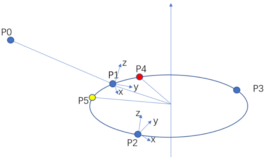
Example 1 MoveJ (p1,v1000, z100, tool1); MoveCF (p2,P3, 360, “RotAxis”, v100, z50, tool1); The starting point P1, and the auxiliary points P2 and P3 jointly define the space circular trajectory. Taking P1->P2->P3 as the positive direction, move 360° along the circle trajectory and return to the P1. During the motion, based on the orientation of starting point P1, rotate accordingly around the center axis of circular trajectory. Example 2 MoveJ (p1,v1000, z100, tool1); MoveCF (p2,P3, -330, “ConstPose”, v100, z50, tool1); Taking P1->P2->P3 as the positive direction, move -330° along the circle trajectory and return to the P5. Maintain the same orientation as P1 during the motion. Example 3 MoveJ (p1,v1000, z100, tool1); MoveCF (p3,P2, 30, “FixedAxis”, v100, z50, tool1); Taking P1->P3->P2 as the positive direction, move 30° along the circle trajectory to the P4. During the motion, based on the orientation of starting point P1, rotate accordingly around the center axis of the circular trajectory but not around its own Z-axis. |
15.4.2.6 MoveT
Explanation |
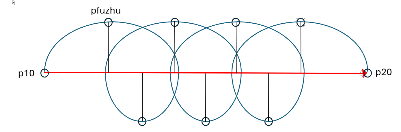
MoveT (Move trochoid) is used to move the TCP to a given target position through rotary stepping with a trochoid passing through auxiliary points. When the starting and ending orientations are different, the orientation will rotate synchronously with the position to the end orientation. The orientation at the auxiliary point does not affect the spiral motion process. Since the translation and rotation speeds are specified separately, the final motion time of the MoveT command depends on the change time of orientation, position, and elbow (whichever is longer) in order not to exceed the specified speed limit. Therefore, in certain trajectories (for example, small displacements but with large changes in orientation), if the robot is moving at a significantly slower or faster speed, check whether the rotation speed setting is reasonable. |
Definition |
MoveT (AuxPoint, ToPoint, Radius, Step, Speed, Zone, Tool, [Wobj]); The parameter in is optional and can be omitted. AuxPoint, Auxiliary Point, data type: robtarget, the position of the auxpoint described in the Cartesian space, used to determine the size of the arc and the direction of motion. The orientation of this point does not affect the execution of the final trajectory. ToPoint, target pose, data type: robtarget, the target position described in the Cartesian space. Radius, cycloid radius, data type: double, radius of trochoid advance, in mm Step, step length, data type: double, step length of trochoid advance, in mm. Speed, Move Speed, data type: speed, to specify the motion speed of the robot when it executes MoveT, including the translation speed of the robot end-effector, the rotation speed, and the motion speed of the external axis. Zone, Turning Zone, data type: zone, to define the size of the turning zone for the current trajectory. Tool, data type: tool, the tool used when executing the trajectory. The speed in the command refers to the tool’s TCP speed and rotation speed. [Wobj], Work Object, data type: wobj, the work object is used to execute the trajectory. When the tool is installed on the robot, this parameter can be ignored; when using external tools, this parameter must be specified, and the robot will calculate the motion speed and the size of the turning zone by using the data saved in wobj. |
Example |
Example 1 MoveL (p10, v1000, fine, tool0); MoveT (pfuzhu, p20, 150, 50, v1000, z50, tool0);
|
15.4.2.7 MoveSP
Explanation |
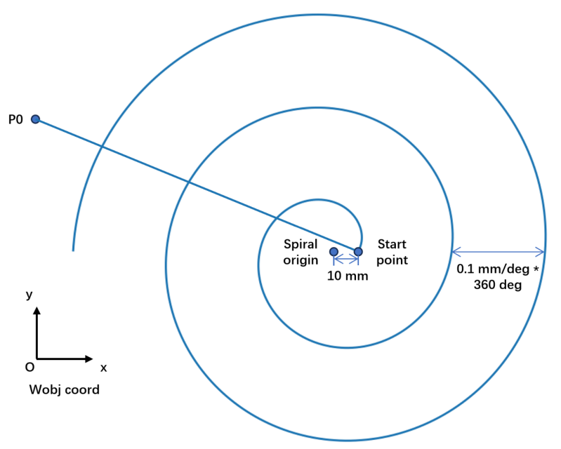
MoveSP (Move Spiral) is used to draw an Archimedean spiral line on the center point TCP of the tool in a plane parallel to the work object frame xy, according to the specified initial radius, rotation increment, total rotation angle, and rotation direction. During the motion process, the orientation changes linearly to the specified orientation at the target point. Note: When the MoveSP command pauses midway and continues to run, it will regenerate the path starting from the current point and no longer continue with the previous path. |
Definition |
MoveSP (Point, Radius, Radius_step, Angle, Direction, Speed, Zone, Tool,[Wobj] ); The parameter in is optional and can be omitted. Point, target point, data type: robtarget, the orientation of Cartesian point position only used as that of the endpoint of the spiral line. Radius, initial radius, data type: double, the initial radius of spiral line, in mm, required to be no less than 0 mm. The center point position of the spiral line is the radius distance of the current position of TCP moving in the negative direction of the x-axis of the work object frame. Radius_step, rotation increment, data type: double, the rotation increment of spiral line, in mm/deg, required to be not less than 0.0001 mm/deg. Angle, total rotation angle, data type: double, the total rotation angle of spiral line, in deg, required to be no less than 0.1 deg and no more than 3600 deg. Direction, rotation direction, data type: int, 0: clockwise outward; 1: counterclockwise outward; 2: clockwise inward; 3: counterclockwise inward. Speed, Move Speed, data type: speed, to specify the motion speed of the robot when it executes MoveSP, including the translation speed of the robot end-effector and the rotation speed. Zone, Turning Zone, data type: zone, to define the size of the turning zone for the current trajectory. The spiral line does not currently support turning zones, and the system will automatically cancel the turning zones before and after the spiral line. Tool, data type: tool, the tool used when executing the trajectory. The speed in the command refers to the tool’s TCP speed and rotation speed. [Wobj], Work Object, data type: wobj, the work object is used to execute the trajectory. When the tool is installed on the robot, this parameter can be ignored; this command only supports external work objects. The TCP motion plane is parallel to the xy plane of the work object frame. |
Example |
Example 1 MoveL (Start_point, v1000, fine, tool1); The robot uses tool1, and TCP starts moving in a straight line Start_point from P0 at a speed of v1000. TCP performs Archimedean spiral line motion at a speed of v100, with the center point located 10 mm in the negative direction of the x-axis of the work object frame from Start_point, and the rotation direction is counterclockwise outward from the center when viewed from the z-axis of the work object frame. The radius increases by 0.1 mm for each 1° of rotation and stops after a total rotation of 900°.
|
15.4.2.8 SearchL
Explanation |
SearchL (Search Liner) is used to search the position when moving the TCP along a straight line. |
Definition |
SearchL ([action][, signal_type][, signal_name] save_rob, target_rob, Speed, Tool [,Wobj]); The parameter in [] is optional and can be omitted. Action, action after triggering DI, data type: keyword, blank: no stop
signal_type, data type: keyword, blank: DI signal
signal_name, data type: DI signal or register, a signal that the SearchL command triggers a specific behavior, using a user-defined DI signal or a register created in the Communication —> Register trigger_mode, DI signal trigger mode, data type: keyword, blank: posedge triggering by default
For numeric registers, 0 indicates a low level and non-0 indicates a high level save_rob, data type: robtarget, to save the point position of the position data when the robot triggers the signal target_rob, data type: robtarget, target point position of linear motion Speed, Move Speed, data type: speed, to specify the motion speed of the robot when it executes Search, including the translation speed of the robot end-effector, the rotation speed, and the motion speed of the external axis. Tool, data type: tool, the tool used when executing the trajectory. The speed in the command refers to the tool’s TCP speed and rotation speed. [Wobj], Work Object, data type: wobj, the work object is used to execute the trajectory. When the tool is installed on the robot, this parameter can be ignored; when using external tools, this parameter must be specified, and the robot will calculate the motion speed and the size of the turning zone by using the data saved in wobj. |
Example |
Example 1 SearchL(di0, save_rob, target_rob, v500, tool0); Example 2 SearchL(\PStop, di0, \Lowlevel, save_rob, target_rob, v500, tool0); The robot uses tool0 and TCP moves at a speed of v500 towards target_rob in a straight line. If di0 jumps to low during the motion, the robot immediately has a planned stop and the robot’s coordinate information at the time of detecting to be low is recorded in save_rob. Example 3 SearchL(\PStop, \Reg, register0, save_rob, target_rob, v500, tool0, wobj1); The robot moves the TCP towards the target_rob in a straight line at a velocity of v500 in wobj1 by using the tool0. If register0 changes from 0 to non-0 during the motion, the robot immediately has a planned stop and the robot’s frame information is recorded in save_rob. |
15.4.2.9 SearchC
Explanation |
SearchC (Search Circle) is used to search for a position when moving the TCP along a circle. During the movement, the robot will monitor a digital input (DI) signal or a read-only register. When the signal status monitored matches the trigger mode, the robot immediately reads the current position. The command can be used when the tool fixed to the manipulator is a probe used for surface detection. Use SearchC command to obtain the outline coordinates of the work object. The command can only be used for motion tasks. |
Definition |
SearchC ([action][, signal_type][, signal_name] save_rob, aux_rob, target_rob, Speed, Tool [,Wobj]); The parameter in [] is optional and can be omitted. Action, action after triggering DI, data type: keyword, blank: no stop
signal_type, data type: keyword, blank: DI signal
signal_name, data type: DI signal or register, a signal that the SearchC command triggers a specific behavior, using a user-defined DI signal or a register created in the Communication —> Register. trigger_mode, DI signal trigger mode, data type: keyword, blank: posedge triggering by default
For numeric registers, 0 indicates a low level and non-0 indicates a high level save_rob, data type: robtarget, to save the point position of the position data when the robot triggers the signal aux_rob, data type: robtarget, auxiliary point of circular motion target_rob, data type: robtarget, target point position of circular motion Speed, Move Speed, data type: speed, to specify the motion speed of the robot when it executes Search, including the translation speed of the robot end-effector, the rotation speed, and the motion speed of the external axis. Tool, data type: tool, the tool used when executing the trajectory. The speed in the command refers to the tool’s TCP speed and rotation speed. [Wobj], Work Object, data type: wobj, the work object is used to execute the trajectory. When the tool is installed on the robot, this parameter can be ignored; when using external tools, this parameter must be specified, and the robot will calculate the motion speed and the size of the turning zone by using the data saved in wobj. |
Example |
Example 1 SearchC (di0, save_rob, aux_rob, target_rob, v500, tool0); The robot uses tool0 and TCP moves at a speed of v500 towards target_rob in a circle after passing auxiliary point aux_rob. If di0 jumps to high during the motion, the robot’s coordinate information at the time of the signal jump is recorded in save_rob. Example 2 SearchC (+PStop, di0, +Flanks, save_rob, aux_rob, target_rob, v500, tool0); The robot uses tool0 and TCP moves at a speed of v500 towards target_rob in a circle after passing auxiliary point aux_rob. If di0 jumps from low to high or from high to low during the motion, the robot immediately has a planned stop, and the robot’s coordinate information at the time of the signal jump is recorded in save_rob. Example 3 SearchC (+Reg, register0, +Flanks, save_rob, aux_rob, target_rob, v5, tool0); The robot moves TCP towards the target_rob in a circle through passing aux_rob at a velocity of v5. If register0 changes from 0 to non-0 during the motion, the robot immediately has a planned stop and the robot’s frame information at the time of the signal jump is recorded in save_rob. |