15.4.19 Function commands
15.4.19.1 CRobT
Explanation |
It is used to get the robot pose. When using this function, you need to give the names of the tool and the work object. Return the pose of the specified tool frame, the current axis configuration information, and the external axis position. |
Definition |
Return value, data type: robtarget, return the current robot position, orientation, axis configuration data, and external axis information. CRobT(Tool, Wobj); Tool, data type: tool, the tool used when calculating the position. Wobj, data type: wobj, the work object used when calculating the position. |
Example |
Example 1 |
15.4.19.2 CJointT
Explanation |
CJointT is used to read the current angle of the robot axes and external axes. Note: When using CJointT, the robot should be in the stop state, i.e. the turning zone of the motion command before CRobT should be set as fine. |
Definition |
Return value, data type: jointtarget, rotation axis unit: degree; linear axis unit: mm, CJointT(); |
Example |
Example 1 |
15.4.19.3 CalcJointT
Explanation |
It is used to calculate the corresponding joint angle based on the specified robtarget variable |
Definition |
Return value, data type: jointtarget, to return the positions of joint angle and external axes corresponding to the input position. The joint angle is in Degrees (°), the external axis of the straight line is in millimeters (mm), and the rotation of the external axis is in Degrees. CalcJointT(Rob_Target, Tool, Wobj); Rob_Target, data type: robtarget, the specified Cartesian space target point. Please note that the tool and work object used in the definition of this point should be consistent with the tool/work object used in the CalcJointT command, otherwise, it may lead to results error. Tool, data type: tool, the tool to be used when calculating the joint angle. Note that it needs to be the same as the one used when defining the robtarget used. Wobj, data type: wobj, the work object to be used when calculating the joint angle. Note that it needs to be the same as the one used when defining the robtarget used. |
Example |
Example 1 Calculate the joint angle when tool1 reaches the pt1 and assign it to jpos2. pt1 is defined under wobj2. |
15.4.19.4 CalcRobt
Explanation |
It is used to calculate the corresponding Cartesian space pose based on the specified joint angle. |
Definition |
Return value, data type: robtarget, to return the Cartesian space pose of a given joint angle. CalcRobt(Joint_Target, Tool, Wobj); Joint_Target, data type: jointtarget, the given joint angle for calculating Cartesian space pose. Tool, data type: tool, the tool used when calculating Cartesian space pose. Wobj, data type: wobj, the work object used when calculating the Cartesian space pose. |
Example |
Example 1 Calculate the Cartesian pose based on jpos1 and assign it to pt1. pt1 is the pose described by the tool frame tool2 in the work object frame wobj1. |
15.4.19.5 Print
Explanation |
It is used to print and output the user-defined content to the teach pendant, and the user can then use this function to debug the program. |
Definition |
Print(var1, var2, ……); |
Example |
Example 1 After the program is executed, the HMI’s program debug window will print the following information: …… Note: When you need to output a string, you can use double quotation marks "" to include the characters you want to display, but nested double quotation marks in double quotation marks are not supported. |
15.4.19.6 Print_f
Explanation |
The Print_f function is similar to the Print command, but it outputs the parameters to a specific log, and users can use this function to record key data and key events of the program. The backup function enables you to export and view the data. The input parameters of the Print_f function are unlimited, but there must be at least one, and each parameter must be a defined variable or a constant. |
Definition |
Print_f(var1, var2, ……); |
Example |
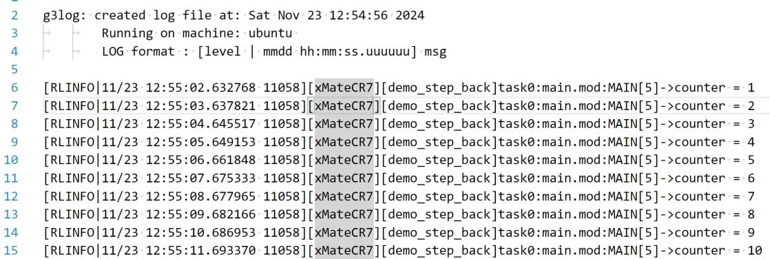
Example 1 After the program is executed, the user log records the changes to the counter, which is available in the exported rl_log.
…… |
15.4.19.7 PoseMult
Explanation |
PoseMult is used to calculate the product of two pose changes |
Definition |
pose3 = PoseMult(pose1, pose2); pose1, data type, pose, pose 1. pose2, data type, pose, pose 2. pose3, return value, data type: pose, the result of pose product. |
Example |
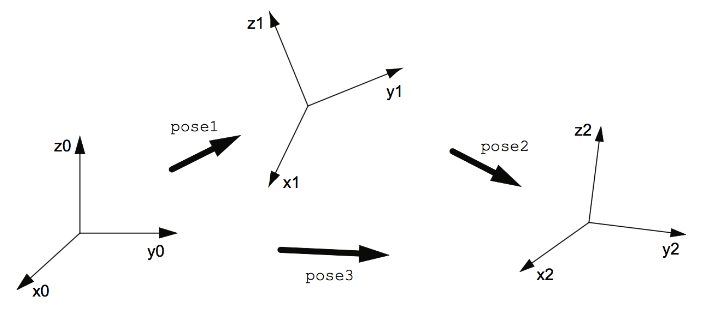
pose1 represents the pose of frame 1 relative to frame 0, and pose2 the pose of frame 2 relative to frame 1. Pose3, the pose of frame 2 relative to frame 0 can be calculated through the following method: |
15.4.19.8 PoseInv
Explanation |
PoseInv is used to calculate the inversion of a pose change. |
Definition |
pose2 = PoseInv(pose1); pose1, data type, pose, input pose; pose2, data type, pose, return value. |
Example |
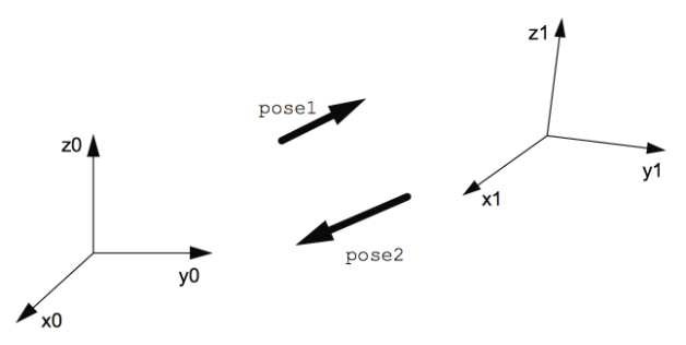
pose1 represents the pose of frame 1 relative to frame 0, and pose 2 the pose of frame 0 relative to frame 1. If pose1 is known, pose2 can be calculated through the following method:
|
15.4.19.9 GetRobABC
Explanation |
Get the Euler angle orientation ABC of the Cartesian space point P; the rotation sequence: the initial frame (the work object frame selected in the motion command) first rotates around its own X axis, then around its Y axis, and last around its Z axis |
Definition |
double db_arr = GetRobABC(Point [, A, B, C]); Point, data type: robtarget, the Cartesian point position used when calculating the position. A, B, C, data type: double, the return value of the Euler angle orientation for the Cartesian point position. Return value, data type: double-type three-dimensional array, the return value of the Euler angle orientation for the Cartesian point position. |
Example |
Example 1 point0 is a Cartesian point position variable. To convert the Euler angle orientation of the variable to a Double variable of RL, use the following RL command Example 2 point0 is a Cartesian point position variable. To generate an array of temporary variables to store the Euler angles of the Cartesian point position, use the following RL command |
15.4.19.10 SetRobABC
Explanation |
Get the orientation of the Cartesian space point P based on the Euler angles ABC entered; the rotation sequence: the initial frame (the work object frame selected in the motion command) first rotates around its own X axis, then around its Y axis, and last around its Z axis. |
Definition |
SetRobABC(Point , A, B, C); Point, data type: Cartesian point position, the Cartesian point position whose orientation to be modified. A, B, C, data type: double, to set the Euler angle orientation for the Cartesian point position, in °. |
Example |
Example 1 point0 is a Cartesian point position variable. Rotate the point position around the fixed axis of X, Y, and Z to 30°, 60°, 90° respectively. |
15.4.19.11 RotRobABC
Explanation |
Rotate the Euler angles from the existing orientation of the Cartesian space point P based on the Euler angles ABC entered; the rotation sequence: the initial frame (orientation of the point P) first rotates around its own X axis, then around its Y axis, and last around its Z axis. The input angles ABC are added to the existing Euler angles. |
Definition |
RotRobABC(Point , A, B, C); Point, data type: Cartesian point position, the Cartesian point position whose orientation to be modified. A, B, C, data type: double, to set the Euler angle orientation for the Cartesian point position, in °. |
Example |
Example 1 point0 is a Cartesian point position variable. Rotate the point position around X, Y, and Z to 30°, 60°, 90°. |
15.4.19.12 OpMode
Explanation |
It is used to obtain the current operating mode of the robot |
Definition |
ret = OpMode(); ret, return value, data type: int, 0: undefined, 1: automatic mode, and 2: manual mode. |
Example |
Example 1 It returns to 1 if it is currently in automatic mode, and returns to 2 if in manual mode. |