10.1 Introduction to this chapter
This chapter mainly introduces various communication settings of the xCore control system, including system IO, registers, bus devices, and end-effector.
10.2 System IO
System IO is divided into two types: system input and system output. The external controller can send various commands to the xCore control system through system input, such as power-on of the motor, start-up of the program, and emergency stop reset. The xCore system can also use system output to send robot status to the outside world, such as power on/off status and operating status.
10.2.1 System input
On the HMI main interface, click "Communication" → "System IO" to enter the system IO settings interface, and click the "System Input" tab to enter the system input configuration interface, as shown in the following figure:
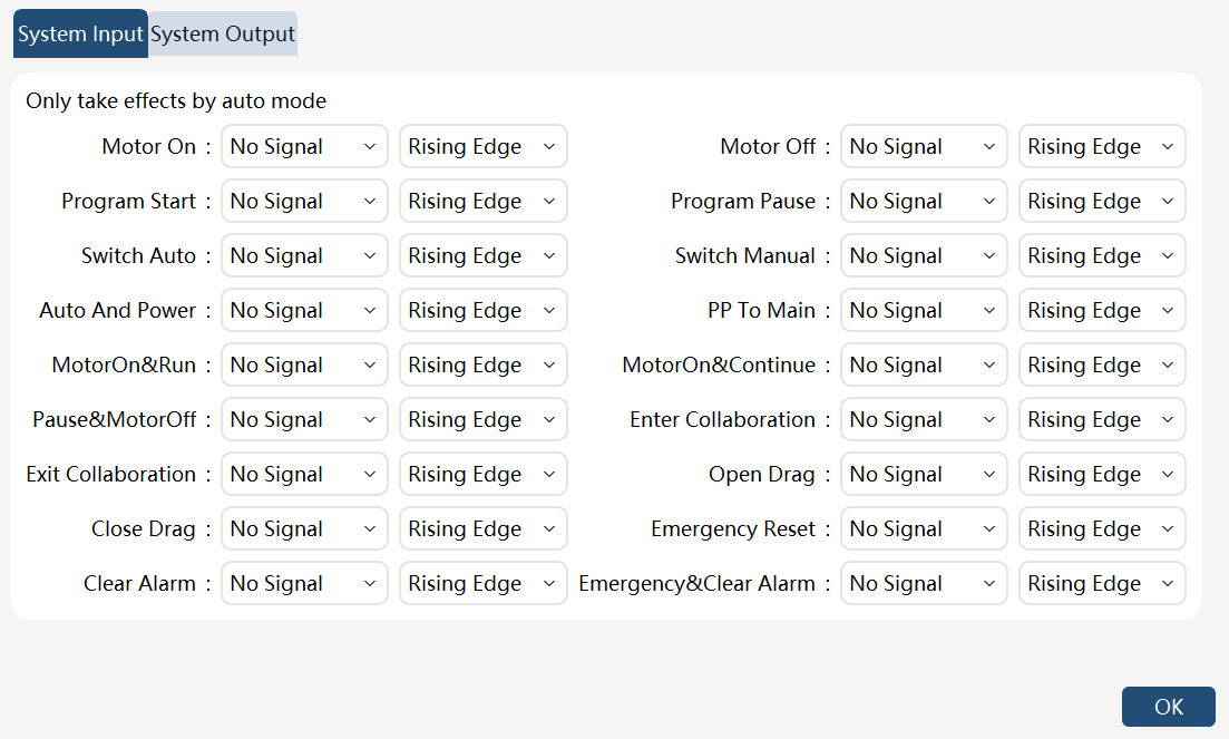
The system inputs supported by the xCore control system are as follows:
System Input |
Trigger Method |
Remarks |
Motor on |
Posedge/Negedge |
|
Motor off |
Posedge/Negedge |
|
Start program |
Posedge/Negedge |
After triggering the function code, if the teach pendant displays the alarm "Program not synchronized to controller, startup failed", synchronize the program and retrigger the function code. |
Program pause |
Posedge/Negedge |
|
Program pause 1 |
Posedge/Negedge |
This function serves the same purpose as the "Pause Program" function |
Switch auto |
Posedge/Negedge |
It is effective in manual mode |
Switch manual |
Posedge/Negedge |
|
Auto and power |
Posedge |
It is effective in manual mode and switches to automatic mode and power on. The robot does not respond to the command when it is in power-on mode. |
PP to main |
Posedge |
|
Motor on & run |
Posedge |
Power on, pptomain, and running in order. After triggering the function code, if the teach pendant displays the alarm "Program not synchronized to controller, startup failed", synchronize the program and retrigger the function code. |
Motor on & continue |
Posedge |
Power on and running in order. After triggering the function code, if the teach pendant displays the alarm "Program not synchronized to controller, startup failed", synchronize the program and retrigger the function code. |
Pause & motor off |
Posedge |
Pause, wait for the robot to stop, and power off |
Enter the reduced mode |
Posedge/Negedge |
Collaborative robot only |
Exit the reduced mode |
Posedge/Negedge |
Collaborative robot only |
Open drag |
Posedge/Negedge |
Collaborative robot only. It is required to enable Drag mode on the interface |
Close drag |
Posedge/Negedge |
Collaborative robot only. It is required to enable Drag mode on the interface |
Emergency reset |
Posedge |
|
Clear alarm |
Posedge |
|
Emergency & clear alarm |
Posedge |
Note:
-
All system inputs are pulse-triggered. To ensure that the xCore system receives external commands correctly, please ensure that the pulse width of the external input is not less than 300 milliseconds.
-
There is a corresponding relationship between the functions that support the triggering of the posedge and negedge (power on, power off, manual mode, automatic mode, start program, pause program, enter collaboration mode, exit collaboration mode, startDrag, and stopDrag) to ensure safety, for example, the functions of "power on" and "power off" are corresponding. If DI1 is selected for "power on", DI1 cannot be used for functions other than "power off".
-
Most system input function is only valid in Automatic mode, and the signal from the system input in manual mode will be ignored.
-
It is not allowed to start the program through any ways when the register equipped with the pause function or system IO has not been reset.
-
The “Pause Program” and “Pause Program 1” functions serve the same purpose. Either function will pause the program upon triggering from any signal path.
10.2.2 System output
On the HMI main interface, click "Communication" → "System IO" to enter the system IO settings interface, and click the "System Output" tab to enter the system output configuration interface, as shown in the following figure:
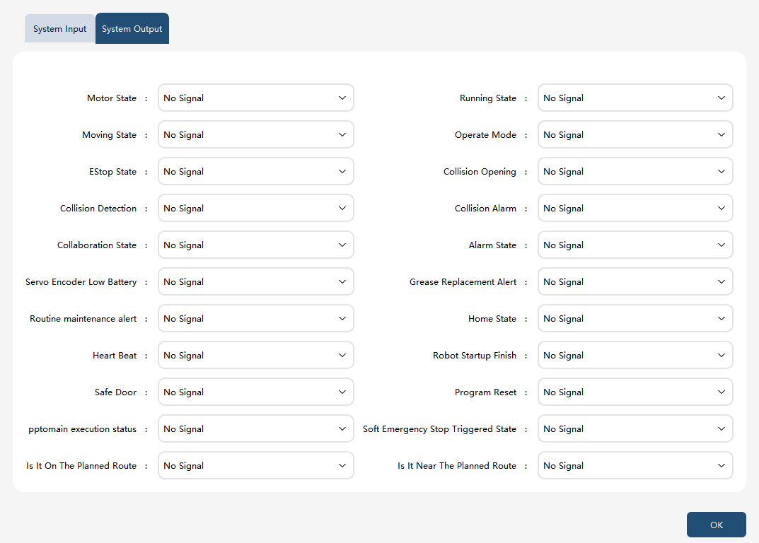
The system outputs supported by the xCore system are as follows:
System Output |
Valid Output |
Invalid Output |
Remarks |
Motor state |
Motor power-on |
Motor power-off |
|
Running state |
Program running |
Program not running |
|
Moving state |
Moving |
Stationary |
Only detect the robot’s motion status when detecting motion commands and Jog in the RL program. (Note: In identification, dragging, force control, and drag playback, even if the robot is in motion, the output is still stationary.) |
Operate mode |
Switch auto |
Manual mode/Wait mode |
|
EStop state |
EStop state |
Non emergency stop |
The output of this state is affected by the "Emergency Stop Trigger Level Type" setting. When it is set to high level, the output is valid when triggering a soft emergency stop, and invalid when not triggered; when it is set to low level, the output is invalid when triggering a soft emergency stop, and valid when not triggered. |
Collision opening |
Open |
Close |
Cobots only |
Collision detection |
Triggered |
Not triggered |
Cobots only |
Collision alarm |
Collision detection alarm triggered |
Alarm reset |
Cobots only |
Reduced mode state |
Reduced mode triggered |
Reduced mode not triggered |
Cobots only |
Alarm state |
Alarm state |
No alarm |
|
Servo encoder low battery |
Low voltage alarm |
Normal voltage |
Maintenance due date of the battery included |
Grease replacement alarm |
Grease replacement required |
No grease replacement required |
Industrial robot only |
Routine maintenance alarm |
Routine maintenance required |
No routine maintenance required |
Industrial robot only |
Home state |
Robot joints at Home |
Robot joints not at Home |
|
Heart beat |
Heart beat |
Click "Settings −> Controller Settings" and set the heartbeat cycle |
|
Robot startup finish |
The robot controller finishes the power-on |
The robot controller does not finish the power-on |
|
Safety door |
Safety gate opened |
Safety gate closed |
|
Program reset |
Program reset |
Program not reset |
|
External estop state |
External estop state |
Non-external estop state |
The safeboard adopts a mini board, and the firmware version is not less than 1.0.8.7 |
Handheld estop state |
Handheld estop state |
Non-handheld estop state |
The safeboard adopts a mini board, and the firmware version is not less than 1.0.8.7 |
PPTOMAIN execution state |
The current program is executing pptomain |
The current program is not executing pptomain |
|
Soft E-stop trigger state |
Soft E-stop trigger state |
Soft E-stop not triggered |
|
On planned path |
Robot’s current position is on the planned path |
Robot’s current position is not on the planned path |
Refer to register function code "sta_on_path" for detailed usage |
Near planned path |
Robot’s current position is near the planned path |
Robot’s current position is not near the planned path |
Refer to register function code "sta_near_path" for detailed usage |
Drag status |
Drag switch enabled |
Drag switch disabled |
Not available for industrial robots |
Status of drag button 1 |
Drag button 1 pressed |
Drag button 1 not pressed |
Not available for industrial robots |
Status of drag button 2 |
Drag button 2 pressed |
Drag button 2 not pressed |
Not available for industrial robots and SR robots. For CR robots equipped with only one drag button, after pressing the drag button, the status outputs of both drag button 1 and drag button 2 are 1. |
Note:
-
The system output status is valid in both manual and automatic modes. However, for safety and availability considerations, these signals are only to be used when the xCore is in Automatic Mode.
-
After an IO point is bound to the system IO, it cannot be forced to output or simulate input operations.
-
All other system output signals are active at a high level except the "Operating Mode" signal.
-
For the signal "Operating Mode", the output is at a high level in Automatic mode and low in Manual mode.