10.7.1 Overview
IO devices support four signal types: DI, DO, AI, and AO. Signal sources include: controller cabinet built-in, EtherCAT expansion, and field bus expansion. For industrial robots, the controller cabinet has several built-in DIs and DOs. For cobots, the base and the end-effector have several built-in DIs and DOs. For industrial robots, the EtherCAT expansion interfaces are reserved on the controller cabinet to connect EtherCAT expansion modules to generate new DI, DO, AI, and AO. The Modbus bus expansion can also be configured with IOs.
10.7.2 Parameter configuration
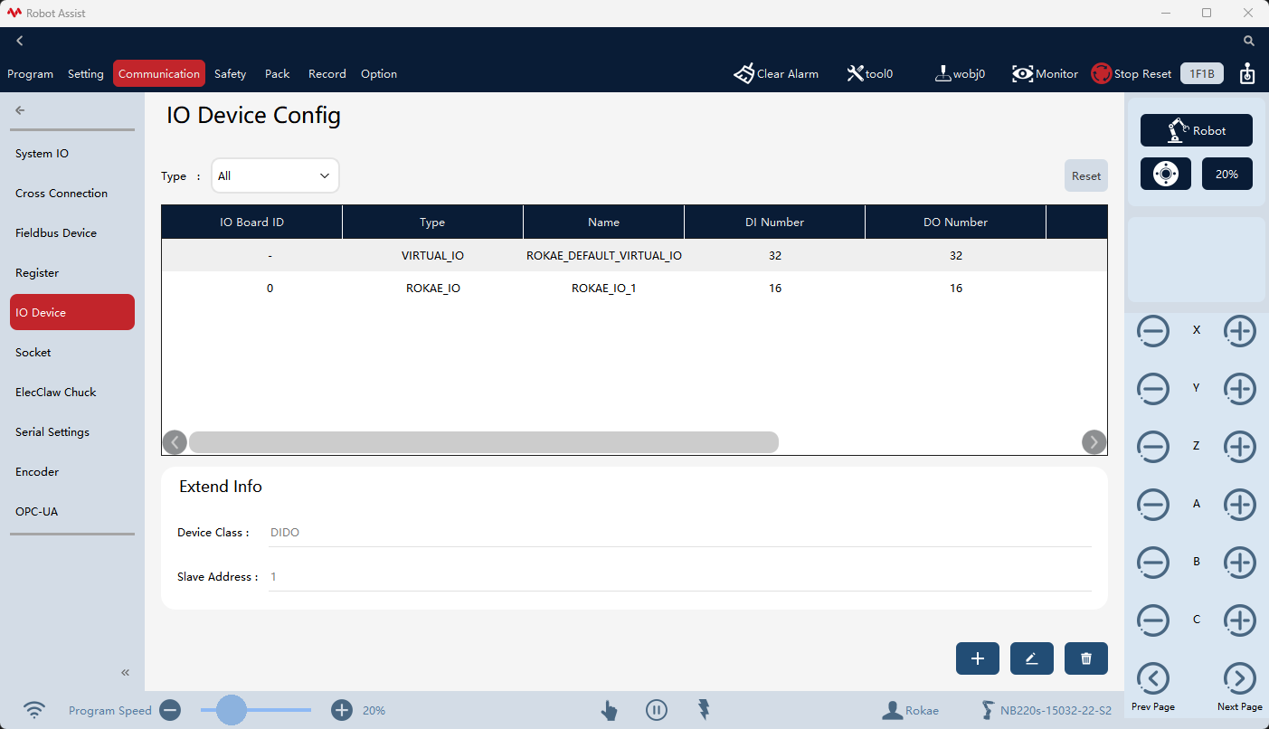
You can view all current IO devices on the "Communication" -> "IO Device" page, and perform operations on them such as Add, Edit, and Delete.
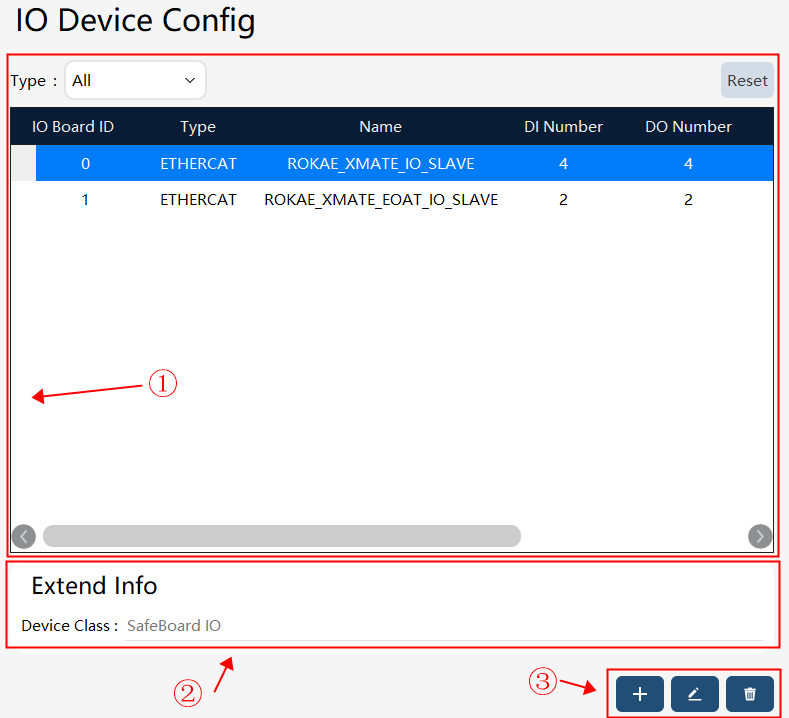
① |
List of IO device. |
② |
IO device extension attributes. |
③ |
The IO device operation buttons, from left to right, are Create, Edit, and Delete. |
Click the Create button in ③ on the IO device configuration page in the above figure to enter the IO device (including ETHERCAT, FIELDBUS, and ROKAE _IO devices) configuration interface. The parameters on the interface may vary with the device type.
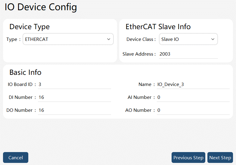
ETHERCAT-Slave IO type device parameter interface
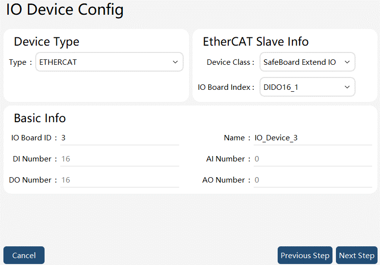
ETHERCAT-SafeBoard Extend IO-DIDO type device parameter interface
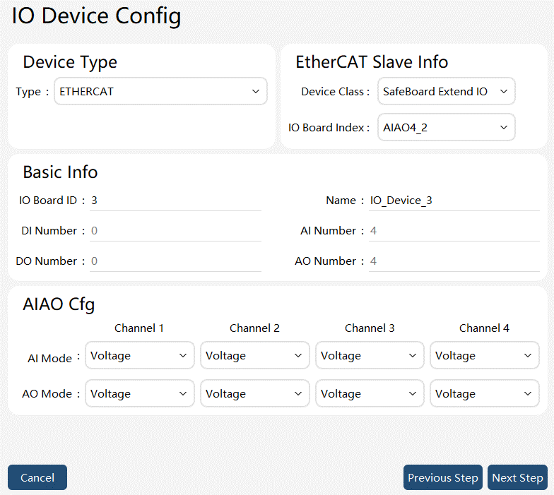
ETHERCAT-SafeBoard Extend IO-AIAO type device parameter interface
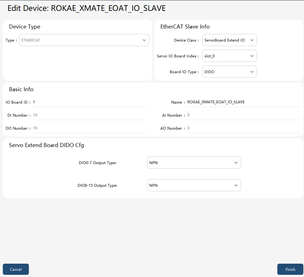
ETHERCAT-ServoBoard Extend IO-DIO type device parameter interface
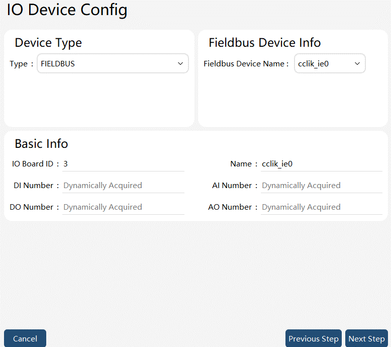
FIELDBUS type device parameter interface
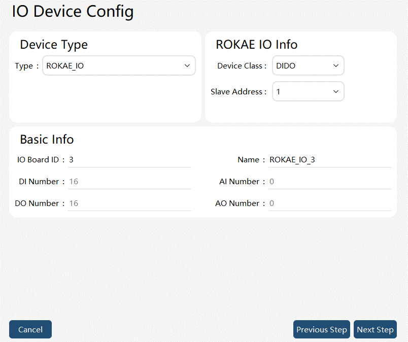
I/O device configuration parameters interface
| Parameter | Explanation |
|---|---|
Device type |
EtherCAT and FIELDBUS are optional. EtherCAT refers to IO expansion with the EtherCAT bus and expansion modules. The expansion modules can only serve as slaves, and the slave address needs to be configured. |
EtherCAT slave information - Device type |
SafeBoard IO, SafeBoard Extend IO, xPanel IO, Slave IO, and ServoBoard Extend IO are optional. SafeBoard IO refers to the DI and DO on the robot safeboard. SafeBoard Extend IO refers to the expansion IO on the robot safeboard, generally the expansion IO on the safeboard in the XBC_5 controller cabinet. xPanel IO refers to the DI and DO of the end-effectors of the cobots. Slave IO refers to the EtherCAT expansion module. ServoBoard Extend IO refers to the extended IO of the robot servo in the XBC_6 control cabinet. |
EtherCAT slave information - IO board type |
When SafeBoard Extend IO is selected in EtherCAT slave information - Device type, the option IO board type appears for selection of the safeboard expansion IO board. DIO16_1, DIO16_4, DIO16_5, DIO16_6, AIAO4_2, and AIAO4_3 are optional. The last digit of the option refers to the address of the safeboard expansion IO board. Select the safeboard expansion IO board that is actually connected. In addition to manual editing by the user, the controller can automatically identify and add the safeboard expansion IO board. |
EtherCAT slave information - Slave address |
The slave address of the expansion module in the EtherCAT bus topology. It should not conflict with the address of the safeboards, joints, or the cobot end-effectors. |
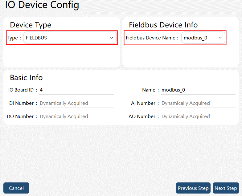
FIELDBUS - Bus device name |
The custom name when a bus connection is created on the Bus Device page. It is used to associate with the Bus Device. |
ROKAE_IO device type |
DIDO and AIAO are optional, corresponding to the digital and analog IO boards developed by ROKAE. Please note that it shall be set according to the actual IO board. |
ROKAE_IO slave address |
It refers to the address of self-developed IO board accessed and ranges from 1 to 15 without repetition. Please note that it shall be set according to the dialing address of the actual IO board, otherwise, there may be an abnormal state. |
IO board serial number |
A virtual IO board is generated for each IO device configuration for the control system to classify and manage the IO boards internally. The IO board serial number is the unique number for virtual IO board management. |
Name |
The custom name of the virtual IO board. It is used for filtering in Status Monitoring -> IO Signal. |
Number of digital inputs |
Number of DIs. |
Number of digital outputs |
Number of DOs. |
Digital IO Configuration |
When ServoBoard Extend IO is selected in EtherCAT slave information - Device type and the IO board type is set to DIO, the digital IO configuration option will appear. The output type of DIO0-7 and DIO8-15 can be configured as either NPN or PNP. Note: This configuration requires a controller restart to take effect. |
Number of analog inputs |
Number of AIs. |
Number of analog outputs |
Number of AOs. |
Analog IO Configuration |
When SafeBoard Extend IO is selected in EtherCAT slave information - Device type and AIAO4_2 or AIAO4_3 is selected in IO board type, the option Analog IO Configuration appears. Each analog channel can be configured as voltage type or current type. |
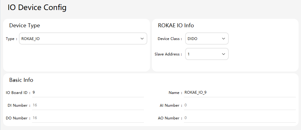
ROKAE_IO type device parameter interface
Monitor the created DI, DO, AI, and AO in Status Monitoring -> IO Signal. The IO signals can be filtered by Virtual IO Board Name. Only the IO signals currently configured on the virtual IO board will be displayed. You can also filter the signals by signal type. Only a certain type of DI, DO, AI, and AO signals will be displayed.
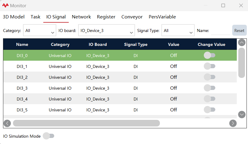
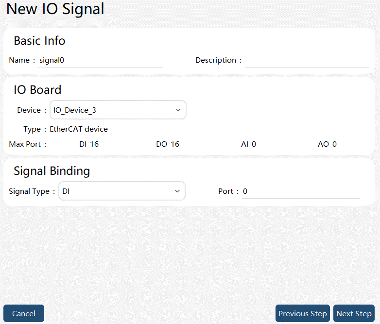
After the virtual IO board is configured, a default name will be generated for the IO signal. There are two ways to use RL: one is to use the default name; the second is to alias and use a new name in RL.
Use the default name |
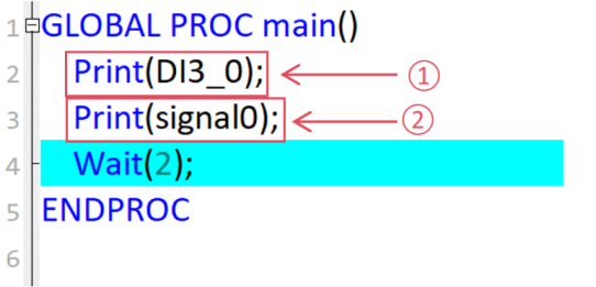
The board IO_Device_3 generates the DI3_X IO signals by default. As shown in the figure, DI3_0 is processed directly in the RL program.
|
Alias |
Alias IO signals in Programming -> IO Signal List:
The statements ① and ② in the above figure have the same effect. |

10.7.3 Virtual IO device
The virtual IO device is a non-physical IO device provided by the ROKAE xCore system. It is built in and is enabled by default upon startup. The core difference between it and physical IO devices is that the reading, writing, and storage of virtual IO device data are all completed within the xCore system, without requiring connection or communication with external devices. In other words, it exists only at the software level and does not correspond to any actual hardware device.
The introduction to the usage methods for virtual IO devices is as follows.
10.7.3.1 Basic usage
Virtual IO is a type of IO device that, similar to other IO devices, features four types of ports: DI, DO, AI, and AO. It allows users to read and write data, create user IO, and bind system IO.
10.7.3.2 Advanced usage
In addition to the basic functions of IO devices, virtual IO also has some additional features. The introduction to the advanced usage methods for virtual IO devices is as follows.
Usage |
Graphical Representation |
Explanation |
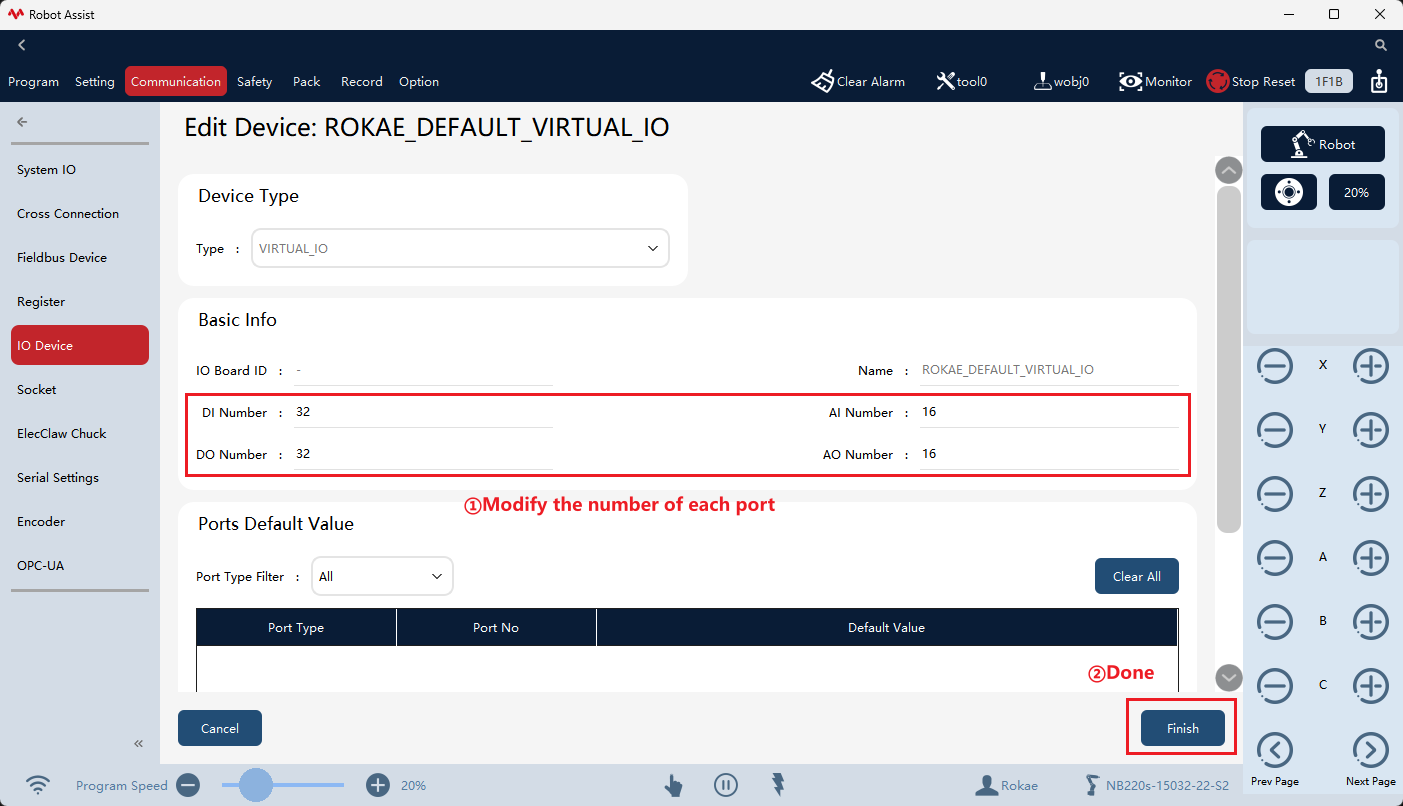
1. Modification of the number of ports |
|
The virtual IO device initially has 32 DI and DO ports, and 16 AI and AO ports. It supports a user-defined number of ports. The valid range for DI and DO ports is [1,512], and for AI and AO ports is [1,16]. Users can modify the number of ports in the IO device configuration interface, and the changes will take effect upon clicking "Complete". |
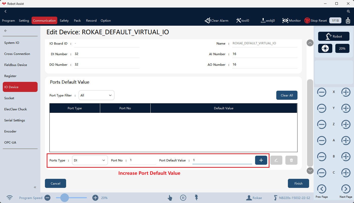
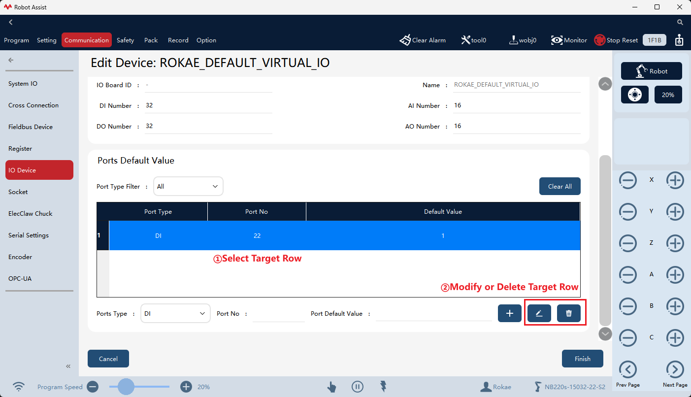
2. Port default value |
|
The port default value is the initial value of each port when the virtual IO device is turned on. Users can configure it as needed. The initial value of DIO ports without default values is 0, and the initial value of AIO ports without default values is 0.0. |
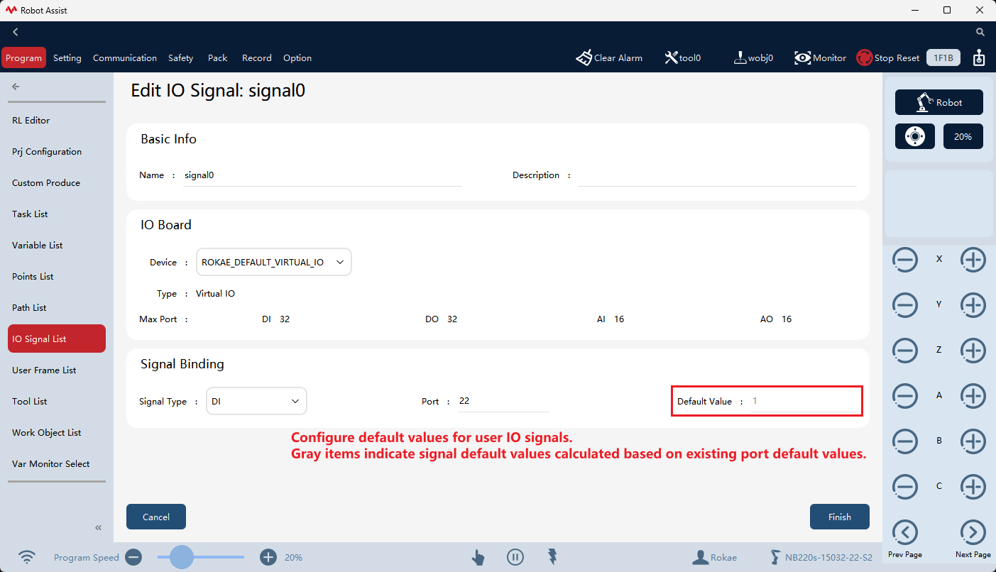
3. Signal default value |
|
The signal default value is the initial value of the signal mapped to the virtual IO device port after system startup. In addition to the port default value, xCore allows users to configure default values for user IO in the project’s IO signal list. |
4. SetVDI command and PulseVDI command |
|
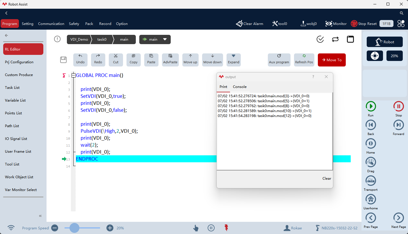
Since virtual IO devices cannot read inputs from external sources, the xCore system provides the SetVDI and PulseVDI commands, allowing users to directly modify the status of virtual IO digital input signals through RL programs. For details on their usage methods and descriptions, refer to the diagram on the left and the IO commands in 15.4.6. |
10.7.3.3 Notes
-
The virtual IO device is unique, comes with the system, and cannot be deleted. Users can only modify the number of its ports;
-
Regardless of whether the user configures default values in the device editing interface or IO signal interface, for ports with default values repeatedly configured, only the last default value configured will be saved and take effect;
-
If the user configures both port default values for a certain port and signal default values for signals mapped to that port, they can confirm the latest configuration information by viewing the port default value list in the virtual IO device editing interface. This list displays the most accurate port default values;
-
The port default value of the virtual IO device takes effect when the virtual IO device restarts. Both the restart of the xCore system and changes in the number of ports in the virtual IO device will lead to the restart of the virtual IO device.
10.7.4 Modbus expansion IO example
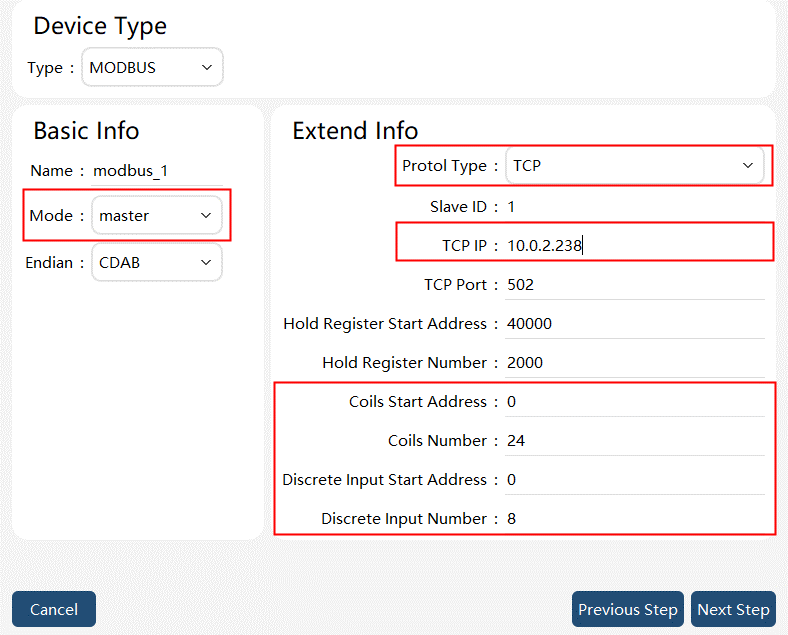
When real IO signals are required to interact with external devices, it is recommended to use an adapter module, which is connected to the control cabinet. You can contact ROKAE to obtain recommended Modbus IO modules. The module is a Modbus TCP slave and controls the robot through the coil function. The robot needs to be configured as a Modbus Master with the coil function enabled.
According to the configuration method of the field bus and expansion IOs, configure Bus Device first and then configure IO Device when using Modbus expansion module to expand real IOs.
| Step | Graphical Representation | Explanation |
|---|---|---|
1. Configure Bus Device. |
|
In master-slave mode, select "Master" to use the robot as a master. |
2. Configure IO Device Configuration. |
|
Select Device Type as "FIELDBUS". |
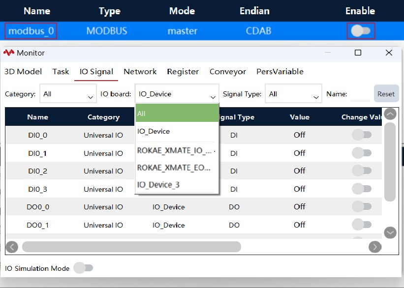
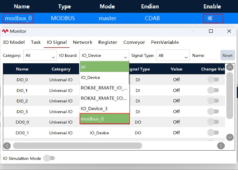
3. Enabling function and status monitoring. |
|
After the Bus Device and IO Device Configuration are just configured, the configured expansion IOs will not be displayed in the status monitoring because the bus connection is not enabled yet. To use these IOs, enable the bus connection to correctly establish connection and communication between the controller cabinet and the expansion IO modules. |