10.6.1 Overview of registers
The register represents the available variables within a robot, which are generally used for data communication with external devices, so as to control the robot and obtain its status. The register can also be used as a variable in the current RL project. The register variables can be operated by commands or assignments.
Note:
-
The register is a concept of robots themselves, rather than belonging to bus devices. A register can be created or edited by specifying which bus device it is bound to for communication.
-
Each register occupies 2 bytes. For different types of variables, the number of registers occupied is different.
10.6.2 Register parameter configuration
On the "Communication" -> "Register" page, you can view existing registers and perform Add, Edit, and Delete.
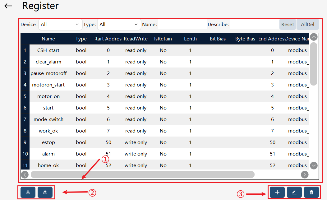
① |
Register list. |
② |
Register import and export button, click to switch to the register import and export page, and perform import and export. |
③ |
The register operation buttons, from left to right, are Create, Edit, and Delete. |

| Parameter | Explanation |
|---|---|
Name |
In RL, register variables can be accessed through this name. |
Type |
bit, byte, bool, int16, float, and int32 are supported. |
Start Address |
The register addresses of the same read and write attributes in the same bus device cannot be cross-occupied, and the register addresses of different read and write attributes in the Modbus bus device cannot be cross-occupied. |
ReadWrite |
ReadWrite attribute, indicating whether the register is read or written from the robot’s perspective (not from the master or slave’s perspective). Write-only registers are used for robot external output status; read-only registers are used by robots to obtain commands sent from external devices. |
IsRetain |
When the register is set to hold, the value of this IsRetain on a non-volatile storage medium during robot restart, shutdown, power outage, or RL stop. When the robot powers on again or RL is running again, the value of register is restored to the value held before the robot shuts down or RL is stopped. |
Length |
The length represents the number of variables. For variables greater than 1, variable references can be made using arrays, with subscripts starting from 1. |
Bit Bias |
Bit Bias represents the position of the bit type register mapped to the register. A register occupies two bytes, which is 16 bits, and the bit offset refers to the position of the corresponding register, with an offset value of 1−16. When creating a bit type register, the bias value can be set if the element number is 1, on the contrary, it cannot be set. |
Byte Bias |
Byte Bias represents the position of the Byte type register mapped to the register. A register occupies two bytes, which is 16 bits, while a byte variable only requires 8 bits. Therefore, when creating a byte register variable, it is necessary to choose whether to map to 8 bits of LSB (1−8) or 8 bits of MSB (9−16) of the register. |
End Address |
The end address represents the last register address occupied by the register variable. When the register variables are arranged continuously, the user can quickly understand the space occupied by the register through this value. |
Device name |
The device name is defined when the "bus device" is created, indicating which bus device is bound to the register. The register can be bound to the CC-Link, CC-Link IE Field Basic, Modbus, and EtherCAT devices. |
Function |
The content in this column is some fixed function codes, indicating the robot function corresponding to this register. Function codes are divided into read-only and write-only function codes, as detailed in the Register Function Code section below. |
The parameters of each column in the register list are explained in the following table:
10.6.3 Register type
| Type | Explanation |
|---|---|
bit |
Only one bit of a register is occupied, and the bit array needs to appear in integer multiples of 16 bits. For example, for a bit type register starting from 41000-bit, a variable with a size of 64 occupies 4 registers from 41000 to 41003. |
byte |
Only a certain 8 bits of a register are occupied, and LSB (the first 8 bits of the register) or MSB (the last 8 bits of the register). When creating a byte register array, the default is LSB, and MSB and LSB cannot be changed. |
bool |
Occupy 1 register. |
int16 |
Occupy 1 register. |
float |
Occupy 2 register. |
int32 |
Occupy 2 register. Note: When the device type is PROFINET, creation is not supported. |
About bit type registers:
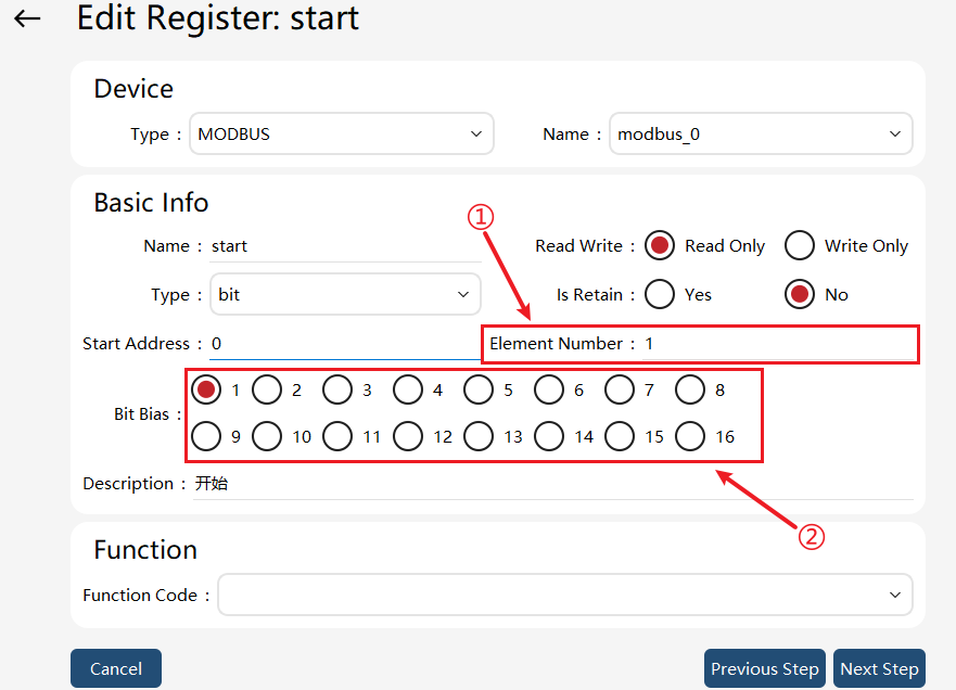
① |
Element Number. |
② |
Bit Bias. As shown in the figure above, if the element number is 1, it indicates that a certain bit of a register is occupied. The number of bit biases can be set, with optional values ranging from 1 to 16. |
When the element number of the bit type register is greater than 1, i.e. the bit variable array, it is not allowed to set the bit bias and perform function binding.
When the input of the element number in a bit type register is greater than 1, the bias option is automatically hidden, and the offset is set to 1.
About byte type registers:
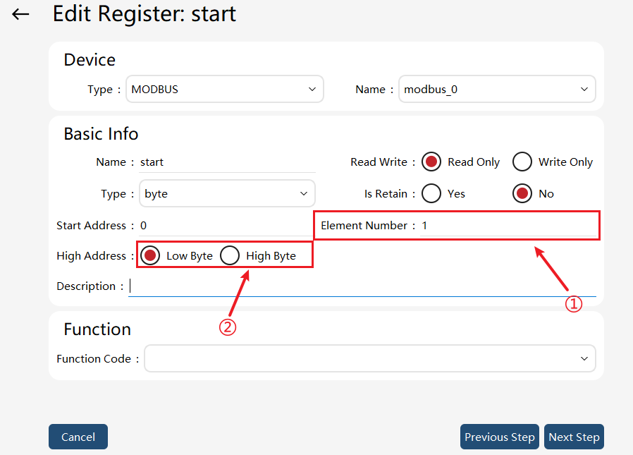
① |
Element Number. |
② |
Byte address. |
As shown in the figure above, if the element number is 1, it indicates that certain 8 bits of a register are occupied, and the byte address can be set, with optional values range of LSB (1-8) and MSB (9-16).
When the element number of the byte type register is greater than 1, i.e., the byte variable array, the byte address is not allowed to be set, with a default of LSB.
Note: It is not allowed to enable the program through the register when it is equipped with the pause function or system IO has not been reset.
10.6.4 Register function code
10.6.4.1 Read-only function code
The read-only function codes are mostly used for control signals, which are usually sent by external devices to the robot to indicate its actions. For robots, these registers are read-only. Currently supported control signals:
Function Code Name |
Supported Binding Types |
Function |
Blank |
N/A |
No function, custom input. |
ctrl_clear_alarm |
bit/bool/byte/int16 |
Clear servo alarms. Posedge (0→1): Clear alarm; set to 0: Reset. |
ctrl_estop_reset |
bit/bool/byte/int16 |
Emergency stop reset. Posedge (0→1): Estop reset; set to 0: Reset. |
ctrl_jjwc_A |
bit/bool/byte/int16 |
The trigger type is pulse trigger, which is active at a high level. When the signal 0->1, the robot stops. After triggering by this signal, the robot cannot continue to run, and can only run again after pptomain, pptofunc, or pptocurs. In addition, the sta_jjwc_B signal is set to 1 (high level). When the signal 1-> 0, the sta_jjwc_B signal is set to 0 (low level). |
ctrl_motor_off |
bit/bool/byte/int16 |
Execution of power off. Posedge (0→1): Power off; set to 0: Reset |
ctrl_motor_on |
bit/bool/byte/int16 |
Execution of power on. Posedge (0→1): Power on; set to 0: Reset |
ctrl_motor_on_off |
bit/bool/byte/int16 |
Motor power on or off: 1, power on; 0, power off. |
ctrl_motoron_pptomain_start |
bit/bool/byte/int16 |
Power on, Pointer to main, and start program in order. |
ctrl_motoron_start |
bit/bool/byte/int16 |
Power on and start program in order. |
ctrl_pause_motoroff |
bit/bool/byte/int16 |
Pause program and execution of power off. Posedge (0→1): Power off; set to 0: Reset. |
ctrl_pptomain |
bit/bool/byte/int16 |
Program pointer to main. Posedge (0→1): Power off; set to 0: Reset. |
ctrl_program_start |
bool/byte/int16 |
Start the RL program. Posedge (0→1): Power off; set to 0: Reset. |
ctrl_program_start_stop |
bit/bool/byte/int16 |
Program running/stop. Set to 1: Program run; set to 0: Program stop |
ctrl_program_stop |
bit/bool/byte/int16 |
Stop the RL program. Posedge (0→1): Power off; set to 0: Reset. |
ctrl_set_program_speed |
bit/bool/byte/int16 |
Set program running rate. Input value represents the running rate. Example: Input "10" sets the rate to 10 |
ctrl_soft_estop |
bit/bool/int16 |
Control the robot’s soft emergency stop, 1: not trigger the soft emergency stop; 0: trigger soft emergency stop. |
ctrl_switch_auto_motoron |
bit/int16/byte/bool |
Switch to Automatic mode first, then power on. Posedge (0→1): Power off; set to 0: Reset. |
ctrl_switch_operation_auto |
bool/byte/int16 |
Switch to Automatic mode. Posedge (0→1): Switch to Automatic mode; set to 0: Reset. |
ctrl_switch_operation_auto_manu |
bit/bool/byte/int16 |
Switch between Automatic mode and Manual mode, set to 1: Automatic mode; set to 0: Manual mode. |
ctrl_switch_operation_manu |
bit/bool/byte/int16 |
Switch to the Manual mode. Posedge (0→1): Switch to Manual mode; set to 0: Reset. |
enable_safe_region01~enable_safe_region10 |
bit/bool/byte/int16 |
Corresponding safe region enabled. Posedge (0→1): Enable safe region; set to 0: Reset |
ext_cmd_set |
bit/bool/int16 |
Remote control function: issue commands. See "Remote Control". |
ext_request_data |
int16 array |
Remote control function: command function code. Array, register with a fixed size of 8. |
ext_reset |
bit/bool/int16 |
Remote control function: overall function reset. See "Remote Control". |
ext_resp_get |
bit/bool/int16 |
Remote control function: Acknowledge and clear the previous command response. |
ctrl_estop_reset_and_clear_alarm |
bit/bool/byte/int16 |
Reset E-stop state and clear alarm. Posedge (0→1): Reset E-stop state and clear alarm; set to 0: Reset. |
ctrl_reduced_mode |
bit/bool/byte/int16 |
Trigger the robot’s reduced mode. Posedge (0→1): Trigger the robot’s reduced mode; set to 0: Reset. |
ctrl_reset_cursor_state |
bit/bool/byte/int16 |
Reset the lookahead pointer change mark (sta_cursor_ste). Posedge (0→1): Reset sta_cursor_state to 0 |
ctrl_change_prog |
int16/int32 |
Trigger the project switch; the input value is the ID value in the project switch list. |
Description: All system inputs of the above system registers are pulse-triggered. To ensure that the xCore system receives external commands correctly, please ensure that the pulse width of the external input is not less than 60 milliseconds.
Preconditions/Precautions |
||
Motor on |
The robot is in automatic mode; |
|
Motor off |
|
|
Program startup |
The robot is in automatic mode; |
|
Program pause |
The external device sends a program pause through a register (without power-off); |
|
Emergency stop handling |
Trigger the emergency stop signal or external emergency stop sequence logic. (Note: After the emergency stop is pressed, the program will stop, the motor will be powered off, and the pointer will be lost, so it is required to clear the alarm, power on, and move the program pointer to main.) |
|
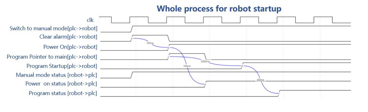
Whole process for robot startup |
Operation sequence: |
|





10.6.4.2 Write-only function code
The write-only function codes are mostly used for state signals, which refer to the signals sent by the robot to the outside world for feeding back the robot’s state, including the power-on state, program state, etc. For robots, a register being write-only indicates that it can be bound to the state signals. The following state signals are currently supported.
Function Code Name |
Supported Binding Types |
Function |
Blank |
No function, custom output. |
|
ext_error_code |
int16 |
Remote control function: error code. |
ext_resp_set |
bit/bool/int16 |
Remote control function: response after command execution. |
ext_response_data |
int16 array |
Remote control function: data to be fed back. Array, register with a fixed size of 8. |
sta_alarm |
bit/bool/byte/int16 |
Servo alarm status, 1: servo alarm; 0: no alarm. |
sta_board_DI0~sta_board_DI3 |
bit/bool/byte/int16 |
Real-time output of signal state of self-developed IO board and Solidot IO board. |
sta_board_DO0~sta_board_DO3 |
bit/bool/byte/int16 |
Real-time output of signal state of self-developed IO board and Solidot IO board. |
sta_collision |
bit/bool/byte/int16 |
Collision detection status, 1: collision detected; 0: no collision. |
sta_collision_alarm |
bit/bool/byte/int16 |
Collision detection alarm, 1: collision detected; 0: no collision; alarm cleared. |
sta_collision_open |
bit/bool/byte/int16 |
Open state of collision detection. 1: Collision detection enabled; 0: Collision detection disabled. |
sta_controller_is_running |
bit/bool/byte/int16 |
Running signal of controller: 1: running controller; 0: controller not running. |
sta_encoder_low_battery |
bit/bool/byte/int16 |
Encoder low voltage alarm status or battery maintenance due date alarm |
sta_grease |
bit/bool/byte/int16 |
Grease replacement alarm status |
sta_routine_maintenance |
bit/bool/byte/int16 |
Routine maintenance alarm status |
sta_error_code |
int16 |
The robot reports an error code, which differs from the error code value in the robot log by 30000. For example, the error code 50002 for the robot log "out of range of motion" was obtained through sta_errorCode as 20002. |
sta_estop |
bit/bool/byte/int16 |
EStop state |
sta_heartbeat |
bit/bool/byte/int16 |
Heartbeat signal, write-only. Click "Settings −> Controller Settings" and set the heartbeat cycle. |
sta_home |
bit/bool/byte/int16 |
Whether each joint of the robot is at the Home point, 1: at the Home point; 0: not at Home point. |
sta_jjwc_B |
bit/bool/byte/int16 |
Real-time state output. Trigger action: passive trigger. When the ctrl_jjwc_A signal is 0->1, the sta_jjwc_B signal is set to 1. When the ctrl_jjwc_A signal is 1->0, the sta_jjwc_B signal is set to 0. |
sta_motor |
bit/bool/byte/int16 |
Motor power on status, 1: powered on; 0: not powered on. |
sta_operation_mode |
bit/bool/byte/int16 |
Current operating mode, 1: Automatic mode; 0: Manual mode. |
sta_program |
bit/bool/byte/int16 |
Whether it is currently in the program running state, 1: program running; 0: free. |
sta_program_full |
byte/int16 |
RL pause state, 0: initialization state; 1: RL running; 2: HMI pause; 3: System IO pause; 4: Register function code pause; 5: External communication pause; 6: SDK pause; 7: Pause command pause; 10: Emergency stop; 11: Safety door; 12: Pause for other factors. |
sta_program_not_run |
bool/byte/int16 |
Non-execution of RL program, 1: non-execution of RL program; 0: execution of RL program. |
sta_program_reset |
bool/byte/int16 |
Program reset success signal; the output is 1 when the program pointer is on the first line of the main function, otherwise, the output is 0. |
sta_program_speed |
int16 |
Query the current program running speed (in percentage terms). |
sta_robot_is_busy |
bit/bool/byte/int16 |
Whether the current robot is performing time-consuming operations such as pptomain, 1: performing; 0: free. |
sta_robot_moving |
bit/bool/byte/int16 |
Whether the robot is in motion, 1: the robot is in motion; 0: the robot is stationary. |
sta_safe_door |
bit/bool/byte/int16 |
The register-bound state signal output is valid when the safety gate is opened, but invalid when the safety gate is closed (active at high level, but inactive at low level). |
sta_safe_jnt_pos1~sta_safe_jnt_pos8 |
bool/byte/int16 |
Safety position triggering state, 1: safety position reached; 0: safety position unreached. |
sta_safe_region01~sta_safe_region10 |
bool/byte/int16 |
Safe region triggering state. 1: Safe region triggered. |
sta_soft_estop |
bit/bool/int16 |
Output of soft emergency stop status. This status value is affected by the emergency stop trigger level type setting. When it is set to high level, the status value is 1 when triggering a soft emergency stop, and 0 when not triggered; when it is set to low level, the status value is 0 when triggering a soft emergency stop, and 1 when not triggered. |
sta_cart_pose |
float array |
Query the current value of the robot tool TCP relative to the world frame. Requirements for bound registers: float array, size - 7. |
sta_cart_vel |
float array |
Cartesian speed of robot. |
sta_jnt_pose |
float array |
Query the current joint angle of the robot. Requirements for bound registers: float array, size - 8. |
sta_jnt_trq |
float array |
Query the current joint torque of the robot. Requirements for bound registers: float array, size - 8, unit: N.m. |
sta_jnt_vel |
float array |
Query the current joint velocity of the robot. Requirements for bound registers: float array, size - 8, unit: rad/s. |
sta_tcp_pose |
float array |
Value of the robot tool TCP relative to the world frame. Requirements for bound registers: float array, size - 7. |
sta_tcp_vel |
float array |
Velocity of the robot TCP. Requirements for bound registers: float array, size - 7. |
sta_tcp_vel_mag |
float |
Robot TCP resultant linear velocity. |
sta_ext_estop |
Bool/byte/int16 |
External estop state |
sta_ext_jnt_pose |
float array |
Query the external axis position
|
sta_hand_estop |
bool/byte/int16 |
Handheld estop state |
sta_sys_stop_di |
bit/bool/byte/int16 |
Output the value of the signal bound to the system pause. "sta_sys_stop_di" outputs 1 when either the "Pause Program" or "Pause Program 1" signal is triggered, and outputs 0 when neither of the two signals is triggered. |
sta_reduced_mode |
bit/bool/byte/int16 |
Whether the robot is currently operating in reduced mode. 1: In reduced mode. |
sta_on_path |
bit/bool/byte/int16 |
Whether the robot’s current position is on the preset trajectory |
sta_near_path |
bit/bool/byte/int16 |
Whether the robot’s current position is near the preset trajectory |
sta_task_state |
int16/int32/byte |
Robot task status output |
sta_drag |
int16/int32/byte/bit/bool |
Whether the robot is in drag status (only applicable for collaborative models) |
sta_drag_button1 |
int16/int32/byte/bit/bool |
Status of robot drag button 1 (only applicable for collaborative models) |
sta_drag_button2 |
int16/int32/byte/bit/bool |
Status of robot drag button 1 (only applicable to non-SR collaborative models) (for CR models with only one button, pressing either sta_drag_button1 or sta_drag_button2 will output 1) 0: Button not pressed |
sta_cursor_state |
bit/bool/byte/int16 |
Whether the lookahead pointer position changes |
sta_tcp_ref_base_vel_mag |
float |
Resultant linear velocity of the TCP relative to the robot base frame, in mm/s; |
sta_tcp_ref_world_vel_mag |
float |
Resultant linear velocity of the TCP relative to the robot world frame, in mm/s; |
sta_tcp_ref_base_pose |
float array |
Pose of the TCP relative to the robot base frame, array length 7 (position in mm, quaternion); |
sta_tcp_ref_world_pose |
float array |
Pose of the TCP relative to the robot world frame, array length: 7 (position in mm, quaternion); |
sta_robot_jnt_pos |
float array |
Robot joint position, array length: 7, in rad or mm; |
sta_robot_jnt_vel |
float array |
Robot joint velocity, array length: 7, in rad/s or mm/s; |
sta_robot_jnt_trq |
float array |
Robot joint torque, array length: 7, in N.mm; |
sta_ext_jnt_pos |
float array |
Additional axis joint position, array length: 6, in rad or mm; |
sta_ext_jnt_vel |
float array |
Additional axis joint velocity, array length: 6, in rad/s or mm/s; |
sta_ext_jnt_trq |
float array |
Additional axis joint torque, array length: 7, in N.mm; |
10.6.5 RL read/write register example
The control system reads and modifies the registers in two ways: command or assignment.
Command provides WriteRegByName and ReadRegByName. Assignment is more intuitive and simple, using the operator "=".
10.6.5.1 Command
WriteRegByName(modbus_reg[index], rl_symbol)
Modbus-reg is the register name configured in "Communication" -> "Register", which can be offset at the first address of the corresponding register using [index]. The index range is [1,maximum register size], and the default index = 1.
The data in the control system can be output to its bound devices through registers.
For example, "int rl_value" is defined in the control system. If you want to output it to an external device, you can specify a register, such as the first register of "mtcp_wo_i", and add a WriteRegByName command in the RL language. The value will be sent to the external device associated with "mtcp _ wo _ i".
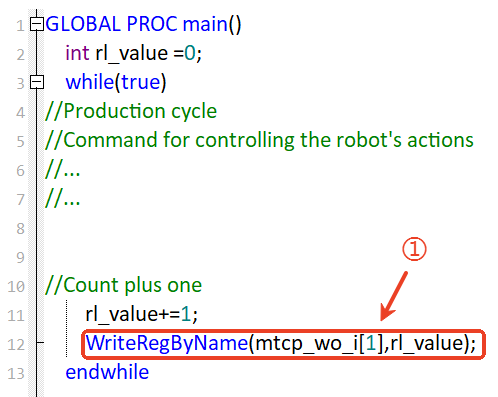
ReadRegByName(modbus_reg[index], rl_symbol)
This command is similar to WriteRegByName, which updates the value of a register to the RL program variable. For example, it is used to control the execution process and motion parameters of RL programs.
10.6.6 Register remote control
Remote control is a combination function performed with registers of 7 different functions. It is used to achieve complex business logic interactions in a specific sequence. External devices can fulfill functions such as robot Jog, updating point position, obtaining robot position and status, etc. via the remote control function.
Register function
External devices use four types of registers to control the robot. These registers are read-only for the robot.
Function Code Name |
Attribute |
Type |
Length |
Function |
ext_cmd_set |
Read-only |
int16/bool/bit |
1 |
Issuing commands: |
ext_reset |
Read-only |
int16/bool/bit |
1 |
Function reset: |
ext_resp_get |
Read-only |
int16/bool/bit |
1 |
Acknowledge and clear the previous command response, and reset ext_resp_set to 0. |
ext_request_data |
Read-only |
int16 |
8 |
Command function code. Array, register with a fixed size of 8. For details, refer to the introduction in the function code section. |
External devices use three types of registers to obtain the robot status. These registers are write-only for the robot.
Function Code Name |
Attribute |
Type |
Length |
Function |
ext_error_code |
Write-only |
int16 |
1 |
Remote control function: error code. |
ext_resp_set |
Write-only |
int16/bool/bit |
1 |
After responding to the control command, the robot sets the register to 1, indicating that the command is executed. |
ext_response_data |
Write-only |
int16 |
8 |
Remote control function: data to be fed back. Array, register with a fixed size of 8. |
10.6.6.1 Procedure
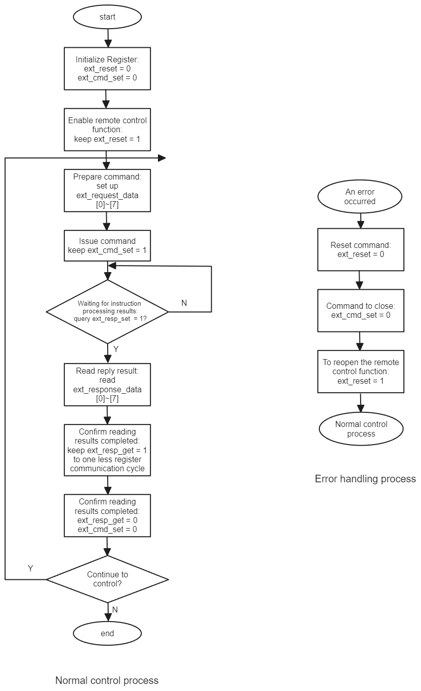
The combined use of 7 types of registers and control flow are shown in the figure below.
10.6.6.2 Command format
Commands and responses are implemented with 8 registers individually.
The command signal ext_request_data (eight registers occupied: reg0 - reg7) is used to specify the data area of the commands and relevant parameters. A command consists of multiple characters:
1) Character: a 16-bit register.
2) Command format: a command consists of up to 8 characters and varies with the command. The shortest command consists of 1 character.
Command No. |
Command No. 1 |
Command No. 2 |
…… |
Command No. 7 |
The response signal ext_response_data (eight registers occupied: reg0 - reg7) is used to obtain the data area of the responses. A response consists of multiple characters:
Command No. |
Response No. 1 |
Response No. 2 |
…… |
Response No. 7 |
1) Character: a 16-bit register.
2) Response format: a response consists of up to 8 characters. and varies with the received command. The shortest response consists of 1 character. However, an abnormal response always occupies 3 characters.
The available command numbers are shown in the table below:
Command Type |
Explanation |
Command Code |
Command Length |
|
|---|---|---|---|---|
Command |
Response |
|||
JOG |
Set Jog space |
1 |
2 |
3 |
Obtain Jog space |
2 |
1 |
4 |
|
Set Jog speed |
3 |
2 |
3 |
|
Obtain Jog speed |
4 |
1 |
4 |
|
Set Jog step length |
5 |
2 |
3 |
|
Obtain Jog step length |
6 |
1 |
4 |
|
Start Jog |
7 |
4 |
2 |
|
Stop Jog (without parameters) |
8 |
1 |
2 |
|
Update point position |
9 |
2 |
2 |
|
Move to point position |
10 |
2 |
2 |
|
Set information |
Set tools |
11 |
2 |
3 |
Obtain current tool id |
12 |
1 |
4 |
|
Set work object |
13 |
2 |
3 |
|
Obtain current work object id |
14 |
1 |
4 |
|
10.6.6.3 Command description
(1) Set Jog space:
Command/Reply |
Command Code |
Parameter 1 |
Parameter 2 |
Set Jog space |
1 |
Frame: |
N/A |
Reply |
1 |
Result: 0 - Succeed; 1 - Fail. |
Error code |
(2) Obtain Jog space:
Command |
Command Code |
Parameter 1 |
Parameter 2 |
Parameter 3 |
Obtain Jog space |
2 |
N/A |
N/A |
N/A |
Reply |
2 |
Result: |
Error code |
Frame: |
(3) Set Jog speed:
Command/Reply |
Command Code |
Parameter 1 |
Parameter 2 |
Set Jog speed |
3 |
Jog speed (1−100) |
N/A |
Reply |
3 |
Result: 0 - Succeed; 1 - Fail |
Error code |
(4) Obtain Jog speed:
Command |
Command Code |
Parameter 1 |
Parameter 2 |
Parameter 3 |
Obtain Jog speed |
4 |
N/A |
N/A |
N/A |
Reply |
4 |
Result: |
Error code |
Jog speed (1−100) |
(5) Set Jog step length:
Command/Reply |
Command Code |
Parameter 1 |
Parameter 2 |
Set Jog step length |
5 |
1: Continuous |
N/A |
Reply |
5 |
Result: 0 - Succeed; 1 - Fail |
Error code |
(6) Obtain Jog step length:
Command |
Command Code |
Parameter 1 |
Parameter 2 |
Parameter 3 |
Obtain Jog step length |
6 |
N/A |
N/A |
N/A |
Reply |
6 |
Result: |
Error code |
1: Continuous |
(7) Start Jog:
The command is dependent on command code 1: set Jog space. In joint space, the value of parameter 1 represents the joint number (J1−J7: 1 for J1, …, 7 for J7); in Cartesian space, it represents the (x, y, z, a, b, c, and elb) number (1 for x, …, 7 for elb).
Command/Reply |
Command Code |
Parameter 1 |
Parameter 2 |
Start Jog |
7 |
Operation mode: |
Jog direction: |
Reply |
7 |
Result: 0 - Succeed; 1 - Fail |
Error code |
(8) Stop Jog:
Command/Reply |
Command Code |
Parameter 1 |
Stop Jog |
8 |
N/A |
Reply |
8 |
Result: 0 - Succeed; 1 - Fail. |
(9) Update point position:
Command/Reply |
Command Code |
Parameter 1 |
Parameter 2 |
Update point position |
9 |
Number in the RL project point list |
N/A |
Reply |
9 |
Result: 0 - Succeed; 1 - Fail |
Error code |
(10) Move to point position:
Command/Reply |
Command Code |
Parameter 1 |
Parameter 2 |
Move to point position |
10 |
Motion mode: |
Number in the RL project point list |
Reply |
10 |
Result: 0 - Succeed; 1 - Fail |
Error code |
(11) Set current tool:
Command/Reply |
Command Code |
Parameter 1 |
Parameter 2 |
Set current tools |
11 |
Number in the RL project tool list |
N/A |
Reply |
11 |
Result: 0 - Succeed; 1 - Fail |
Error code |
(12) Obtain current tool id:
Command/Reply |
Command Code |
Parameter 1 |
Parameter 2 |
Parameter 3 |
Obtain current tool id |
12 |
N/A |
N/A |
N/A |
Reply |
12 |
Result: 0 - Succeed; 1 - Fail |
Error code |
Current tool id |
(13) Set current work object:
Command/Reply |
Command Code |
Parameter 1 |
Parameter 2 |
Set current work object |
13 |
Number in the RL project work object list |
N/A |
Reply |
13 |
Result: 0 - Succeed; 1 - Fail |
Error code |
(14) Obtain current work object id:
Command/Reply |
Command Code |
Parameter 1 |
Parameter 2 |
Parameter 3 |
Obtain current work object id |
14 |
N/A |
N/A |
N/A |
Reply |
14 |
Result: 0 - Succeed; 1 - Fail |
Error code |
Current work object id |
10.6.6.4 Error code
During command configuration, parameter errors, robot status mismatch, or other conditions may lead to configuration failure. Error codes can be used to check the robot’s problems in this case.
The control system has three types of error codes:
ext_response_data: error code of command execution results.
ext_error_code: The command cannot be executed, for example, the robot is busy, or the remote control flag bit is incorrect, etc.
sta_error_code: the robot error code. Read the register when an error occurs during Jog.
Normally, the error code should be used according to the following steps:
After sending the execution command (ext_cmd_set=1), first read ext_error_code. If there is no error code, read the return value of ext_response_data. If the return value is not zero, read the error code of ext_response_data.
For motion operations (Jog and move to point position), if the above return values are both 0, read sta_error_code to see if there is a stop in the motion caused by an error (such as singularity and overrun).
ext_error_code description:
| Error code | Meaning | Remarks |
|---|---|---|
01 |
Unsupported command |
|
02 |
Invalid parameter |
|
03 |
Incorrect control flag bit |
Check whether ext_resp_set is 0 or 1. |
04 |
Robot busy |
The robot is executing a command and is forbidden to respond to others. |
05 |
No corresponding number found |
Tool, point position, and work object id |
06 |
Unmatched point type and motion type |
The point type does not match the motion type for the "Move to point position" command. For example, only the MoveAbsJ command can be used for joint space points, and only the MoveJ or MoveL command can be used for Cartesian space points. |
07 |
Unmatched number of axes entered and model |
|
11 |
Incorrect Manual/Auto Mode |
|
12 |
Incorrect robot status. Please check if the robot is in Jog Mode. |
The robot can only be jogged in Jog Mode and can not be jogged in non-Jog Mode such as Drag Mode. |
13 |
Incorrect power-on status |
The robot can only be jogged when powered on. |
14 |
The robot is in non-position mode and can not be jogged |
Similar to error code 12. |
15 |
Report algorithm error when unable to start Jog |
The error is reported when the robot cannot be jogged for various reasons. |
20 |
Encounter singularity |
|
21 |
Moved to target point |
If the robot moves to a point it has reached earlier, an error occurs. |
10.6.7 Register import and export
The register import and export function can quickly copy register configurations from one robot to another robot without reconfiguring registers.
10.6.7.1 Register export
On the register page, click the button in the bottom left corner  to enter the register export interface
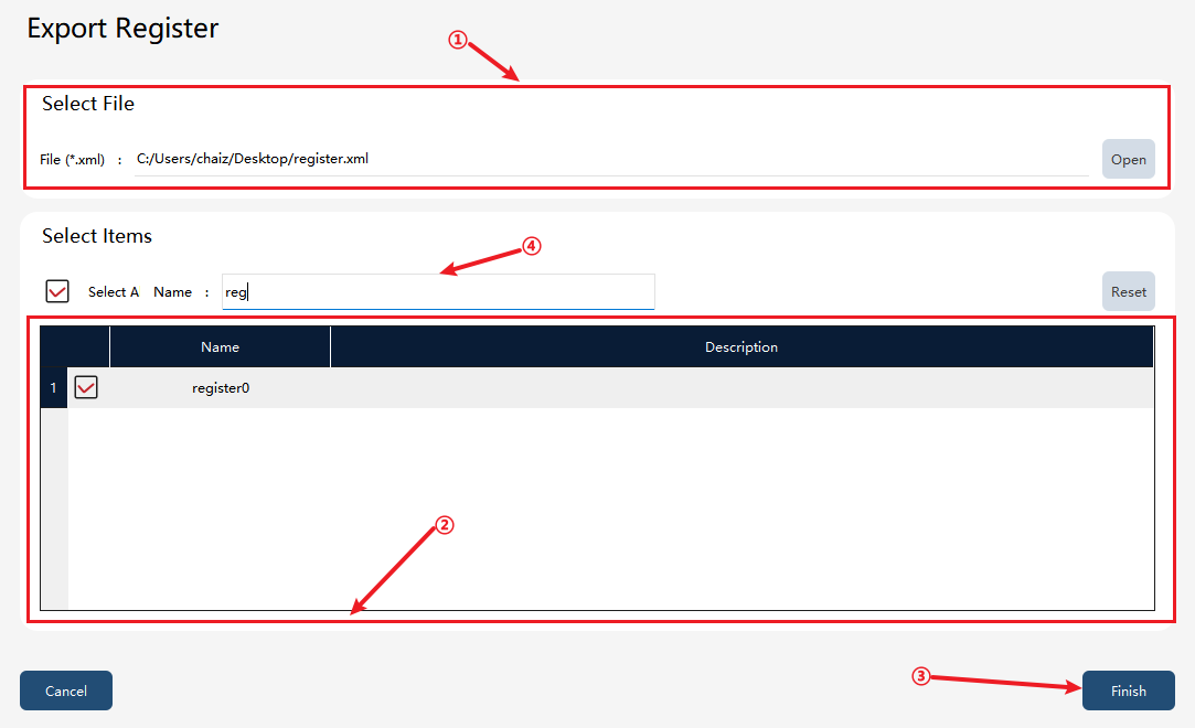
① |
Register export target file (including path). |
② |
Register export selection list. |
③ |
Register export operation button. |
④ |
Filter box, supporting entire and partial export |
Export steps: First, enter or select the register export target file path in ①, then check the register to be exported in the register list in ②, and finally click the "Finish" button in ③ to execute the export. The exported register file can be generated under the corresponding path in ①.
10.6.7.2 Register import
On the register page, click the button in the bottom left corner  to enter the register import interface
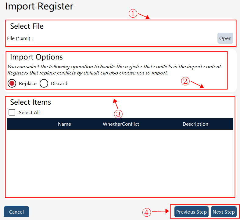
① |
Register import file. |
② |
Register import options, which are strategies for handling conflicting items. |
③ |
Register import selection entry. |
④ |
Register import operation button. |
Import steps: First, select the register file to be imported in ①, then set the conflicting register strategy in ②, then select the register to be imported in ③, and finally click the "Next Step" in ④ to perform the import to import the selected register to the local machine.
10.6.7.3 Conflict checking during register import
The same device and register properties (read and write) cannot have the same register address. If the same, if the import option is set to not import, the original register will prevail, and conflicting registers will not be imported; if the import option is set to auto replace, the newly imported register will prevail, and the conflicting register will be overwritten. A pop-up window will prompt the user to choose whether to replace the current register.
When creating the 7 registers starting with ext: ext_cmd_set, ext_resp_set, ext_resp_get, ext_reset, ext_response_data, ext_request_data, and ext_error_code, if the register has been bound by the register address, these addresses cannot be bound by another register. When importing the above 7 registers, if the function codes have already been bound in the HMI, and the newly imported register list also involves such function codes, the newly imported ones will prevail, and the original conflicting register will be overwritten. A pop-up window will prompt the user to choose whether to replace the current register.