15.4.18 Advanced commands
15.4.18.1 RelTool
Explanation |
It is used to translate or rotate the spatial position in the tool frame as specified by the current command. Main difference from Offs: Offs is the offset relative to the work object frame, and RelTool is the offset relative to the tool frame. |
Definition |
Return value, data type: robtarget, to return the new pose after the offset. RelTool(Point, XOffset, YOffset, ZOffset, Rx, Ry, Rz [, Tool, Wobj]); Point, data type: robtarget, the point to be offset, or the initial point of the offset command. XOffset, data type: double, offset in the x-direction of the tool frame. YOffset, data type: double, offset in the y-direction of the tool frame. ZOffset, data type: double, offset in the z-direction of the tool frame. Rx, data type: double, the rotation angle around the x-axis of the tool frame. Ry, data type: double, the rotation angle around the y-axis of the tool frame. Rz, data type: double, the rotation angle around the z-axis of the tool frame. Tool, data type: tool, contain tool frame information describing the Point position. Wobj, data type: wobj, contain work object frame information describing the Point position. |
Example |
Example 1 Since no tool and work object is specified, tool0 and wobj0 are used by default. Offset point p1 by 100 mm in the x-direction, 0 mm in the y-direction, and 30 mm in the z-direction on the tool frame, and then rotate 20 degrees around the x-axis. Last assign the new target point position to p2. Example 2 Offset point p1 by 100 mm in the x-direction, 0 mm in the y-direction, and 30 mm in the z-direction on the tool5 tool frame, and then rotate 20 degrees around the x-axis. Last assign the new target point position to p2. Example 3 RelTool is used along with the Move command. As no tool or work object frame is specified, the tool and wobj of the Move command will be used. Offset point p1 by 100 mm in the x-direction, 0 mm in the y-direction, and 30 mm in the z-direction on the tool2 tool frame, and then rotate 20 degrees around the x-axis. |
Attention |
Auxiliary programming is not supported for the optional parameters (Tool and Wobj) of this command. The 5-axis models of the xMate CR series may have many unreachable points when using the RelTool command due to the lack of one orientation DOF. It is necessary to determine the offset based on the characteristics of reachable orientations (e.g. translation of points is usually reachable where the flange remains parallel to the base). |
15.4.18.2 Offs
Explanation |
The position offset function, which is used to offset a point in the work object frame specified in the current command by a distance and return the position value of a new point. The translation offset is represented by x, y, and z, and the orientation rotation offset is represented by Rx, Ry, and Rz. |
Definition |
Return value, data type: robtarget, the new pose after the offset. Offs (Point, XOffset, YOffset, ZOffset [, Rx, Ry, Rz] ) Point, data type: robtarget, the point to be offset, or the initial point of the offset command. XOffset, data type: double, offset in the x-direction of the work object frame. YOffset, data type: double, offset in the y-direction of the work object frame. ZOffset, data type: double, offset in the z-direction of the work object frame. Rx, data type: double, the rotation angle around the x-axis of the work object frame. Ry, data type: double, the rotation angle around the y-axis of the work object frame. Rz, data type: double, the rotation angle around the z-axis of the work object frame. |
Example |
Example 1 Have the point p10 offset 100 mm in the x-direction, offset 200 mm in the y-direction, offset 300 mm in the z-direction of the work object frame, and assign the position of the new target point to p11. |
Attention |
This command does not support auxiliary programming for the moment. |
15.4.18.3 ConfL
Explanation |
After the command is enabled, the following two items are checked:
|
Example |
Example 1 |
Attention |
|
15.4.18.4 ConfJ
Explanation |
The Cartesian frame corresponds to a set of conf parameters (cf1−7, cfx). The conf data corresponding to the Cartesian coordinate points manually changed or written by the user may be incorrect, which makes it impossible for the controller to resolve the path of the target point. But in some scenarios, the user cares only about the robot’s TCP position rather than the orientation. In this case, ConfJ Off can be used to remove conf limitations of the point and the controller can try to calculate the inverse kinematics closest to the starting point of the path (the calculation may fail, resulting in a failure of the motion command). Users can read the introduction to confdata for details of conf. |
Example |
Example 1 |
Attention |
The ConfJ command corresponds to MoveJ, without impact on the other motion commands, or the conf setting of "Move to". |
15.4.18.5 Conf
Explanation |
Effect of unified ConfL and ConfJ on/off: Conf on: equivalent to ConfL on and ConfJ on Conf off: equivalent to ConfL off and ConfJ off |
Example |
Example 1 |
15.4.18.6 VelSet
Explanation |
The VelSet command allows for adjusting maximum motion speed for smoother motion when the robot is handling fragile objects. Instead of being constant, the maximum velocity of each joint keeps changing with load, body orientation, and other factors when the robot is moving. The VelSet command scales the maximum velocity capability curve for a specific task path, and the scaled maximum velocity capability curve is also a changing curve. |
Definition |
VelSet (gain); gain, data type: int, the maximum velocity capacity is specified in percentage, ranging from 1% to 100%, where 100% means the maximum acceleration. The robot reports an error when going over the limit. |
Example |
Example 1 Set the maximum velocity capability to half of the robot’s default maximum velocity. |
Attention |
1. The VelSet command only affects the motion commands of the corresponding RL project, instead of JOG, move to, rapid motion, and other non-project functions. 2. The VelSet function will interrupt the turning zone. Please do not insert VelSet commands between the motion commands that require a turning zone. 3. The difference between the VelSet command and the program running rate adjustment slide: the program running rate adjustment slide modifies the user’s expected velocity, for example, motion command V4000, under 50% slide control, equals a user’s expected velocity of V2000. But if the robot is at its limits, the actual maximum velocity of this motion command is only V1000, then the actual motion velocity of the robot does not change regardless of whether the velocity slide is at 50% or 100% because both V2000 and V4000 are above V1000. Changing the expected velocity during this range will not impact the actual execution velocity; on the contrary, VelSet 50 does not change the user’s expected velocity but reduces the actual maximum velocity of the motion command by 50% during the motion planning process. Under the same motion command, the actual motion velocity of the robot will be cut to half from V1000 to V500. The user should identify the difference between these two functions. 4. Speed automatically reverts to the default (100%) during the following operations:
|
15.4.18.7 AccSet
Explanation |
The AccSet command allows for adjusting acceleration for smoother movement when the robot is handling fragile objects. |
Definition |
AccSet (acc, ramp); Acc, data type: int, the acceleration is specified as a percentage of the system preset value, ranging from 30% to 100%, where 100% means the maximum acceleration, beyond which the robot will stop and report an error. Ramp, data type: int, the Jerk is specified as a percentage of the system preset value, ranging from 30% to 100%, where 100% means the maximum jerk, beyond which the robot will report an error. |
Example |
Example 1 Acceleration and jerk are set to half of the default. |
Attention |
Acceleration automatically reverts to the default (100%) during the following operations:
|
15.4.18.8 MotionSup
Explanation |
It is used to turn on and off Collision Detection. |
Definition |
MotionSup(type [, level, event]); Type, data type: keyword, On: turn on, Off: turn off Level, data type: int, the additional parameter for MotionSup On to modify the collision detection sensitivity percentage, range [1, 200]: Event, data type: string, the additional parameter for MotionSup On to set the behavior after collisions
|
Example |
Example 1 After enabling collision detection, users can execute other commands and turn off collision detection by MotionSup Off after the completion of commands Example 2 Users enable collision detection and set the detection sensitivity percentage to 200% and the behavior triggered to a compliant stop after detecting a collision. |
15.4.18.9 MotionSupPlus
Explanation |
MotionSupPlus (Motion Supervision Plus) is used to adjust the robot’s joint collision detection sensitivity in the RL program at any time. |
Definition |
MotionSupPlus(x1, x2, x3, x4, x5, x6, x7); x1 to x7, the collision detection sensitivity in % for joints 1-7, respectively. |
Example |
Example 1 Indicates the sensitivity of the 7 joints to be 5, 20, 7, 20, 6, 20, 5, respectively. Note: For 6-axis robots, 7 parameters should be set too, where the first 6 parameters correspond to joints 1-6. This command is available for cobots and six-axis industrial robots, but not three- and four-axis industrial robots. |
15.4.18.10 MotionSupJointTrq
Explanation |
MotionSupJointTrq (Motion Supervision Joint Torque) Motion supervision is used to adjust the driving torque limits of robot joints at any time in the RL program. |
Definition |
MotionSupJointTrq(x1, x2, x3, x4, x5, x6, x7); x1 to x7 indicates the driving torque limits of joint 1 to joint 7 respectively, in N.m. |
Example |
Example 1 It indicates that the driving torque limits of 7 joints are 100 N.m, 91 N.m, 59 N.m, 14 N.m, 14 N.m, 14 N.m, and 5 N.m, respectively. Note: For 6-axis robots, 7 parameters should be set too, where the first 6 parameters correspond to joints 1-6. This command is available for cobots and six-axis industrial robots, but not three- and four-axis industrial robots. |
15.4.18.11 BreakLookAhead
Explanation |
This command informs the control system to cancel the lookahead and force the cancellation of the turning zone between the previous motion command and the next motion command. The robot TCP will move to the target point position of the previous motion command and then move to the next point without the turning zone. The program pointer will also wait for the TCP to move to the target point position of the previous motion command before continuing the lookahead scan. |
Definition |
The command includes no parameters and no return value |
Example |
Example 1 1) The turning zone of point P1 is set to z50. Because of the BreakLookAhead command, the lookahead and the turning zone will be canceled, and the robot TCP will move exactly to point P1 and then to P2. There is no BreakLookAhead command between P2 and P3, so the robot will look ahead at P2 and pass the z50 turning zone before moving to P3. 2) The BreakLookAhead command has the same effect as the wait 0 command. |
15.4.18.12 GetRobotMaxLoad
Explanation |
It is used to get the maximum load value of the current robot model. |
Definition |
Ret = GetRobotMaxLoad(); Ret, return value, data type: int, maximum payload |
Example |
With xMate 7 as an example, return 7. |
15.4.18.13 GetRobotState
Explanation |
It is used to get the current operating state of the control system. Use the 4-byte bit information to represent the state of the control system, including fault, emergency stop, safety gate, operation mode, servo mode, and motion state, as shown in following table. |
Definition |
Ret = GetRobotState(); Ret, return value, data type: byte array, use four-byte types to represent the robot state. |
Example |
Example 1 Return {0, 5, 0, 0}. According to the table, the current state is: no fault, motor powered on, automatic mode, robot motion state, servo is in position mode. |
S/N |
State bits |
Meaning |
1 |
Byte[1].bit[1] |
1: Control system is not authorized |
2 |
Byte[1].bit[2] |
1: Control system recoverable faults |
3 |
Byte[1].bit[3] |
1: Control system fatal error |
4 |
Byte[1].bit[4] |
1: Servo system failure |
5 |
Byte[1].bit[5] |
1: Servo system fatal failure |
6 |
Byte[1].bit[6] |
1: Emergency stop |
7 |
Byte[1].bit[7] |
1: Safety gate stop |
8 |
Byte[1].bit[8] |
Reserved |
9 |
Byte[2].bit[1] |
Power-on state, 0: motor is not powered on; 1: motor is powered on |
10 |
Byte[2].bit[2] |
Robot motion state, 0: idle; 1: in motion |
11 |
Byte[2].bit[3] |
Operation mode, 0: manual mode; 1: automatic mode |
12 |
Byte[2].bit[4] |
Servo mode, 0: position mode; 1: torque mode |
13 |
Byte[2].bit[5] |
Reserved |
14 |
Byte[2].bit[6] |
Reserved |
15 |
Byte[2].bit[7] |
Reserved |
16 |
Byte[2].bit[8] |
Reserved |
17 |
Byte[3] |
Reserved |
18 |
Byte[4] |
Reserved |
15.4.18.14 AutoIgnoreZone
Explanation |
It is used to specify whether to allow the control system to automatically ignore the turning zone. |
Definition |
AutoIgnoreZone (true/false); true: Allow the control system to automatically ignore the turning zone (This is also the default state of the control system); false: Do not allow the control system to automatically ignore the turning zone
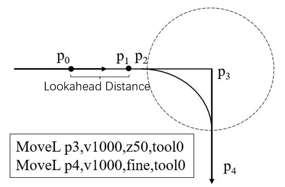
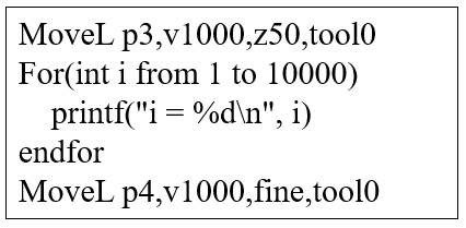
As shown above: The robot runs two MoveL commands with a z50 turning zone in between. During the motion, the robot needs lookahead from its current position for smooth and safe motion. For example, when the robot moves to p0, it looks ahead to P1. In this process, the control system pre-processes the information between p0 and p1. As the robot moves forward, the lookahead end point also moves forward. At a certain point, the lookahead end point p1 coincides with p2, the start point of the turning zone. If the control system has received the second motion command, it can generate a turning zone properly and control the robot to move along the predetermined trajectory; if the control system fails to receive the second motion command, it cannot generate the turning zone, and it will process the turning zone according to the AutoIgnoreZone command status. See below for the logic: AutoIgnoreZone true: Instead of waiting for the second motion command, the control system will cancel the turning zone and control the robot to move directly toward P3. AutoIgnoreZone false: The control system will wait for the second motion command, during which the robot will slow down until the turning zone trajectory is generated. If the robot fails to receive the second motion command when reaching P2, the robot will stop moving and report an error through HMI. The failure of the robot to receive the second motion command timely is often a result of too many non-motion commands between two motion commands, e.g.:
Many print commands are added between two motion commands, and it takes a long time for the control system to receive the second motion command after the first one is processed. |
Example |
Example 1 Allow the control system to automatically ignore the turning zone Example 2 Do not allow the control system to automatically ignore the turning zone |
15.4.18.15 MotionWaitAtFinePoint true/false
Explanation |
When the robot is stationary and the user clicks Start, the control system will look ahead a certain distance according to the lookahead parameter before starting the robot. This command sets whether the robot starts moving immediately when the lookahead coincides with a fine point. Fine point: the target point without a turning zone, i.e. a target point with the turning zone parameter set to fine. |
Definition |
MotionWaitAtFinePoint(true/false); MotionWaitAtFinePoint true: The control system controls the start of the robot strictly according to the lookahead parameters. The robot only starts to move when the lookahead distance reaches the set value of the lookahead parameter or the lookahead of all motion commands is completed. In this state, the control system can guarantee the set lookahead distance. MotionWaitAtFinePoint false: The control system does not strictly follow the lookahead parameters, and the robot starts moving immediately when the lookahead coincides with the fine point. In this state, the robot can still start smoothly when the program logic gets extremely complicated, but the lookahead distance cannot be guaranteed. Default: MotionWaitAtFinePoint false |
Example |
Example 1 When the control system looks ahead to p1, it does not start the robot immediately, but checks whether the current lookahead distance has reached the set length before deciding whether to start the robot. Example 2 When the control system looks ahead to p1, it immediately starts the robot, instead of checking whether the current lookahead distance has reached the set length. |
15.4.18.16 IgnoreOverride
Explanation |
In scenarios where welding, gluing, and other processes have strict requirements for the motion speed along the path, the command is developed with the hope of the motion speed of the process section not being affected by the global speed. This command can temporarily block the influence of the rate slider on motion commands, so that a specific segment of motion commands and trajectories is not affected by the global speed. This command supports performance in both automatic and manual modes. In manual mode, the motion speed is limited by v250. If the speed exceeds v250, it moves at v250. In automatic mode, it moves at the desired speed. |
Definition |
IgnoreOverride(On/Off); IgnoreOverride On indicates that subsequent motion commands are not affected by the rate slider, and IgnoreOverride Off has the opposite effect. |
Example |
Example 1 Example 2 (manual mode) Example 3 (automatic mode) |
Attention |
Affected motion commands: MoveAbsJ, MoveJ, MoveL, MoveC, MoveCF, MoveT, SearchL, SearchC, TrigL, TrigC, and TrigJ. The command is not immediately executed and does not interrupt the turning zone. It can only be used in motion tasks and cannot be used in Inzone; otherwise, an error will be reported. |
15.4.18.17 SingAreaLockAxis4
Explanation |
This command indicates the use of locking the 4-axis method to avoid robot wrist singularities. |
Definition |
SingAreaLockAxis4(on/off ); SingAreaLockAxis4 on indicates the enabling of the 4-axis locking to avoid wrist singularity function. It should be noted that this function can only be enabled when the 4-axis of the robot is at 0° or ±180°. It is necessary to ensure that the 4-axis is at the target point of the previous motion command of SingAreaLockAxis4 on or that the 4-axis of the robot is already at the above angle to ensure normal program operation, otherwise, an error will be reported. Off, the function is turned off. Note: The Cartesian motion command between SingAreaLockAxis4 on and SingAreaLockAxis4 off adopts a special interpolation method for its pose, without changing the motion angle of the 4-axis. Any motion command attempting to change the 4-axis angle will cause an error. At the same time, this command is designed as a blocking command, which will interrupt the turning zone between the front and rear motion commands of SingAreaLockAxis4. The current version is applicable to industrial standard six-axis series (XB, NB models) and collaborative xMateCR, xMateSR series (excluding 5-axis models). This command is not supported when full DH compensation is enabled. |
Example |
Example 1 Point position p1 needs to ensure that the 4-axis angle is 0° or ±180°. When running to SingAreaLockAxis4, the 4-axis locking for wrist singularity avoidance function is enabled. The MoveL p2 and MoveL p3 will adopt the special interpolation method for their poses to maintain the 4-axis angle unchanged. SingAreaLockAxis4 off indicates to close the function. |
15.4.18.18 SpeedRefresh
Explanation |
It is used to override the speed value in the current motion program task. |
Definition |
SpeedRefresh(override); override, data type: int, value range: [1%, 100%], if the speed override value exceeds the limit range, the robot will report an error. |
Example |
Example 1 It indicates the current speed override value is set to 70% |
Attention |
|
15.4.18.19 CSpeedOverride
Explanation |
It indicates the current speed override value that users read |
Definition |
Ret = CSpeedOverride(); Ret Data type: int The value range is 1%−100% of the speed override value |
Example |
Example 1 If the current speed override value is 70%, it will return to 70 |
15.4.18.20 SingAreaJointWay
Explanation |
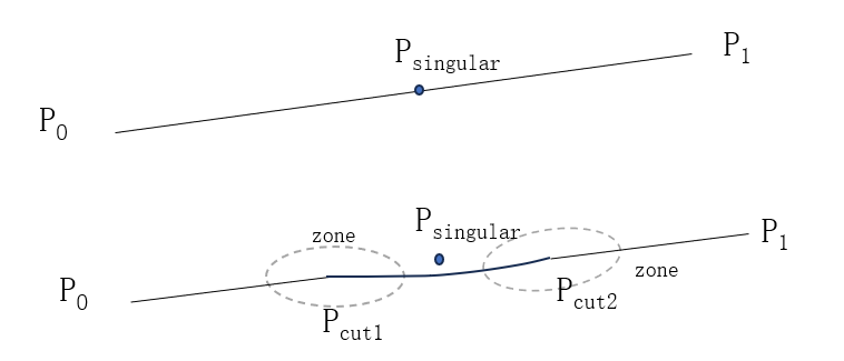
It indicates the use of joint space trajectory interpolation to avoid singularities in Cartesian commands. The Cartesian motion command between SingAreaJointWay on and SingAreaJointWay off will be automatically detected by the control system for any singularity. If the trajectory does not contain singularities, it will move in the same way as a normal trajectory. If it contains singularities, it will move in a unique pattern specific to the mode. See below for details:
As shown in the above figure, for the Cartesian trajectory P0P1 with singularities, the control system detects the singularity Psingular and adds two points, Pcut1 and Pcut2, around the singularity Psingular, to the original trajectory. The original trajectory is divided into three parts: P0Pcut1, Pcut1Pcut2, and Pcut2P1. Among them, P0Pcut1 and Pcut2P1 are still in the original Cartesian trajectory, but Pcut1Pcut2 uses a joint space trajectory (MoveAbsJ) instead of the original trajectory, so that it can traverse the singularity. The three trajectory segments are smoothly transitioned using a turning zone, and the turning radius of the turning zone can be set, which is the zone parameter in the command. The motion of robot near singularities usually involves a large range of joint angles, so when using this command, it is necessary to confirm whether the robot’s motion trajectory meets the requirements. Note: The current version is applicable to industrial standard six-axis series (XB, NB models). |
Definition |
SingAreaJointWay(on/off, zone); on/off, to indicate that the joint interpolating singularity is enabled or disabled. Zone, to indicate the radius of the turning zone for the three trajectory segments P0Pcut1, Pcut1Pcut2, and Pcut2P1 after cutting, as shown in the above figure, referring to the definition of the turning zone. |
Example |
Example 1 In the above commands, SingAreaJointWay on, 50 enables singularity avoidance and specifies an internal turning radius of 50 mm for singularity avoidance. SingAreaJointWay off disables singularity avoidance, and the motion commands in between will use the method of joint interpolating singularity avoidance for motion. |
15.4.18.21 SingAreaWrist
Explanation |
This command indicates using sacrifice orientation to avoid singularities in Cartesian commands. The Cartesian motion commands between SingAreaWrist on and SingAreaWrist off both use sacrifice orientation to move. In this case, the robot tool follows the correct and precise trajectory motion, but the shape of the robot’s wrist will be altered. When the singularity is not traversed, the above situation will also occur. The robot uses sacrifice orientation to move, and the wrist orientation of the robot may have a large range of motion. Therefore, when using this command, it is necessary to confirm whether the robot’s motion trajectory meets the requirements. Note: The current version is applicable to industrial standard six-axis series (XB, NB models) and collaborative xMateCR, xMateSR series. |
Definition |
SingAreaWrist(on/off, limit); Limit, the value in degrees that represents the maximum allowable sacrifice orientation. |
Example |
Example 1 In the above commands, SingAreaWrist on, 30 enables singularity avoidance and specifies the maximum sacrifice orientation of 30 degrees for singularity avoidance. SingAreaWrist off disables singularity avoidance, and the motion commands in between will use the method of singularity avoidance for motion. Please note that the turning zone between p1 and p2 and between p2 and p3 can be generated normally, while the turning zone between p3 and p4 cannot be generated. |
Attention |
It can only be used for linear motion, not for curved motion. When using the sacrifice orientation for singularity avoidance function, the teaching point will be changed when it is within the singularity range. The wrist orientation during motion may sometimes differ from the taught orientation, not only at the teaching points where singularities are traversed, but also potentially at subsequent teaching points. The motion of the orientation near the singularity may differ between single-step motion and continuous motion. |
15.4.18.22 SetRobotJointsMaxAcc
Explanation |
It is used to dynamically modify the maximum acceleration of the robot joint. When the robot needs to magnify the maximum acceleration of the joint to raise the takt and increase the robot’s motion speed, the maximum acceleration of each joint can be set by this command. The effect of this command is consistent with the "maximum joint acceleration" under the motion parameters set on HMI, and this command is available for a specific motion. |
Definition |
SetRobotJointsMaxAcc(jointval1, jointval2, jointval3, jointval4, jointval5, jointval6, jointval7 ); jointval1−7, data type: double/int, maximum acceleration of the joint, unit: °/s2. |
Example |
Example 1 |
Attention |
When there is a turning zone between the two motion commands, the turning zone is generated according to the constraints of the smaller one between the maximum joint accelerations. |
15.4.18.23 SetRobotJointsMaxJerk
Explanation |
It is used to dynamically modify the maximum jerk of the robot joint. When the robot needs to magnify the maximum jerk of the joint to raise the takt and increase the robot’s motion speed, the maximum jerk of each joint can be set by this command. The effect of this command is consistent with the "maximum joint jerk" under the motion parameters set on HMI, and this command is available for a specific motion. |
Definition |
SetRobotJointsMaxJerk(jointval1, jointval2, jointval3, jointval4, jointval5, jointval6, jointval7 ); jointval1−7, data type: double/int, maximum jerk of the joint, unit: °/s3. |
Example |
Example 1 |
Attention |
When there is a turning zone between two trajectory segments, the turning zone is generated according to the constraints of the smaller one between the maximum joint accelerations; |
15.4.18.24 SetTransmissionOverloadParams
Explanation |
It is used to dynamically modify the driving overload coefficient of the robot. When the robot needs to magnify the driving overload coefficient of the joint properly to raise the takt and increase the robot’s motion speed, the driving overload coefficient of each joint can be set by this command. The effect of this command is consistent with the "overload coefficient" under the body parameters set on HMI, and this command is available for a specific motion. |
Definition |
SetTransmissionOverloadParams (jointval1, jointval2, jointval3, jointval4, jointval5, jointval6, jointval7); jointval1−7, data type: double/int, driving overload coefficient of the joint. |
Example |
Example 1 |
Attention |
When there is a turning zone between two trajectory segments, the turning zone is generated according to the constraints of the smaller one between the transmission overload coefficients; |
15.4.18.25 ResetTransmissionOverloadParams
Explanation |
Used to restore the robot’s transmission overload coefficient to its original value; to be used in conjunction with the SetTransmissionOverloadParams command; the effect of this command is cleared after taking effect; |
Definition |
ReSetTransmissionOverloadParams(); No parameters. |
Example |
Example 1 |
15.4.18.26 SetAccRampTime
Explanation |
It is used to set the acceleration ramp time, that is, the time it takes for the robot to increase its acceleration from a minimum to a maximum. The smaller the value, the faster the robot accelerates, and vice versa. |
Definition |
SetAccRampTime (ramptime); ramptime, data type: double/int, acceleration ramp time, range: , unit: s. |
Example |
Example 1 |
15.4.18.27 ResetAccRampTime
Explanation |
It is used to reset the acceleration ramp time, with the SetAccRampTime. |
Definition |
ResetAccRampTime (); No parameters; |
Example |
Example 1 |
15.4.18.28 SetVarValue
Explanation |
It is used to assign the variables in the turning zone, and the assignment is not triggered for lookahead. |
Definition |
SetVarValue(var1, var2); Assign var2 to var1. var1: data type: byte, int, double, bool, and writable register variable with no function code bound. var2: data type: byte, int, double, bool, IO variable, register variable, function return value, and expression. |
Example |
Example 1 |
Attention |
The implicit conversion occurs during the assignment. For example, after the assignment, the variable a is 20. |
15.4.18.29 SetStopAccRampTime
Explanation |
It is used to set the acceleration ramp time during the final stop phase. For target points without a turning zone, this is the time it takes for the robot to increase its acceleration from a minimum to 0 during the final stop phase. The smaller the value, the faster the robot stops, and vice versa. If the acceleration ramp time is greater than the acceleration ramp time during the final stop phase, the robot will use the longer acceleration ramp time for stopping. |
Definition |
SetStopAccRampTime(ramptime); ramptime, data type: double/int, acceleration ramp time during the final stop phase, range: [0.01, 1], unit: s. |
Example |
Example 1 |
15.4.18.30 ResetStopAccRampTime
Explanation |
It is used to reset the acceleration ramp time during the final stop phase, with the SetStopAccRampTime. |
Definition |
ResetStopAccRampTime(); No parameters; |
Example |
Example 1 |
15.4.18.31 PathRecStart
Explanation |
Start recording the robot’s path. It is a stop lookahead command. After executing PathRecStart to initiate path recording, the supported motion types for recording include MoveL, MoveJ, MoveAbsJ, MoveC, TrigL, TrigC, and TrigJ. During path recording, the execution of MoveC and TrigC commands cannot be interrupted; otherwise, the target points cannot be recorded. If MoveC or TrigC commands are interrupted, an error will be reported and execution will stop. |
Definition |
PathRecStart(); |
Example |
When lookahead reaches PathRecStart, it stops lookahead and waits for the motion before PathRecStart to complete before executing PathRecStart. Motion commands after this command will be recorded. |
15.4.18.32 PathRecStop
Explanation |
Stop recording the robot’s path and clear the recorded path data. It is a stop lookahead command. |
Definition |
PathRecStop(); |
Example |
When lookahead reaches PathRecStop, it stops lookahead and waits for the motion before PathRecStop to complete before executing PathRecStop. After this command, path recording will cease and the recorded path data will be cleared. |
15.4.18.33 PathRecBwd
Explanation |
Make the robot move backward along the recorded path. It is a stop lookahead motion command, and the motion of PathRecBwd will not be recorded. If there are commands that interrupt lookahead between motion instructions, when executing the recorded path, the turning zone of the trajectory before the lookahead interrupting command will be set to z0. After executing PathRecStart to initiate path recording, if an interrupt is triggered, the PathRecBwd command in the interrupt must precede other motion commands; otherwise, an error will be reported and execution will stop. PathRecBwd cannot be interrupted. If an interrupt is triggered while executing PathRecBwd, an error will be reported and execution will stop. |
Definition |
PathRecBwd(); |
Example |
Two motion commands are recorded after PathRecStart. When executing PathRecBwd, the robot will perform path backtracking, moving from j2→p1→the robot’s position when executing PathRecBwd (j1) |
15.4.18.34 PathRecFwd
Explanation |
Make the robot move backward to the position where PathRecBwd was executed. It is a stop lookahead motion command, and the motion of PathRecFwd will not be recorded. If there are commands that interrupt lookahead between motion instructions, when executing the recorded path, the turning zone of the trajectory before the lookahead interrupting command will be set to z0. After executing PathRecStart to initiate path recording, if an interrupt is triggered, the PathRecFwd command in the interrupt must not be followed by any motion commands; otherwise, an error will be reported and execution will stop. PathRecFwd cannot be interrupted. If an interrupt is triggered while executing PathRecFwd, an error will be reported and execution will stop. |
Definition |
PathRecFwd(); |
Example |
When executing PathRecBwd, the robot performs path backtracking . At this point the robot is at position j1. When executing PathRecFwd, the robot will move from j1->p1->j2 back to position j2. |
15.4.18.35 GetRecStartStatus
Explanation |
Get whether path recording is enabled. The return value is of bool type |
Definition |
GetRecStartStatus(); |
Example |
Get whether path recording is enabled. true if enabled, false if disabled. |
15.4.18.36 SetMaxMotionJerk
Explanation |
Set the value of the robot’s underlying otgc jerk. The default value is 300. Increasing this value can achieve faster start/stop effects. The value will be restored to default after pptomain; |
Definition |
SetMaxMotionJerk(Num); Num: Data type: int/double, greater than 100 |
Example |
Example 1 |
15.4.18.37 VibSuppression
Explanation |
Command to set the vibration suppression function switch. During Pptomain, the vibration suppression function reverts to the state set in the HMI interface (see the vibration suppression function in the Dynamic settings module in 9.8). |
Definition |
VibSuppression(Type); Type, data type: keyword, on: turn on, off: turn off |
Example |
When executing the VibSuppression(on) command, the controller enables the vibration suppression function. The movements at subsequent points p1−p3 will be affected by the vibration suppression function, where robot vibrations during start/stop are suppressed, resulting in improved trajectory accuracy. When executing the VibSuppression(off) command, the controller disables the vibration suppression function. |