变量类型
15.1.1 Int
Explanation |
The range of the integer int variable is -2147483647−2147483647. It is recommended that the value is within the specified range. If the value is in excess of the range, it will be assigned randomly, and the maximum value range must not be exceeded when using it. |
Example |
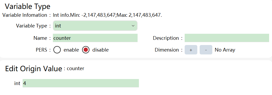
In the variable list:
It represents the data counter that defines an integer global variable type, and its initial value is 4. |
15.1.2 Double
Explanation |
Floating-point numbers, are stored using 8 bytes. Do not exceed the value range when using them. |
Example |
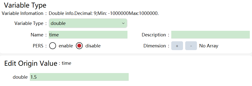
In the variable list:
It represents the local variable time that defines a floating point, and its initial value is 1.5. |
15.1.3 Bool
Explanation |
The variable bool is mainly used for status or logic judgments. The value is true or false. When it is assigned an int or double value, non-zero takes the value of true and zero takes the value of false. |
Example |
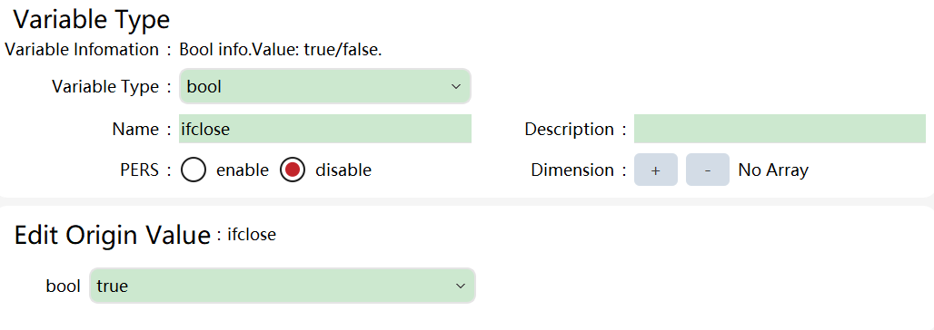
In the variable list:
It indicates that a bool type global variable ifClose is defined and the initial value is true. |
15.1.4 String
Explanation |
String-type variables consist of multiple letters or numbers. Note: They must be placed in double quotation marks "" at the time of defining in RL text. |
Example |
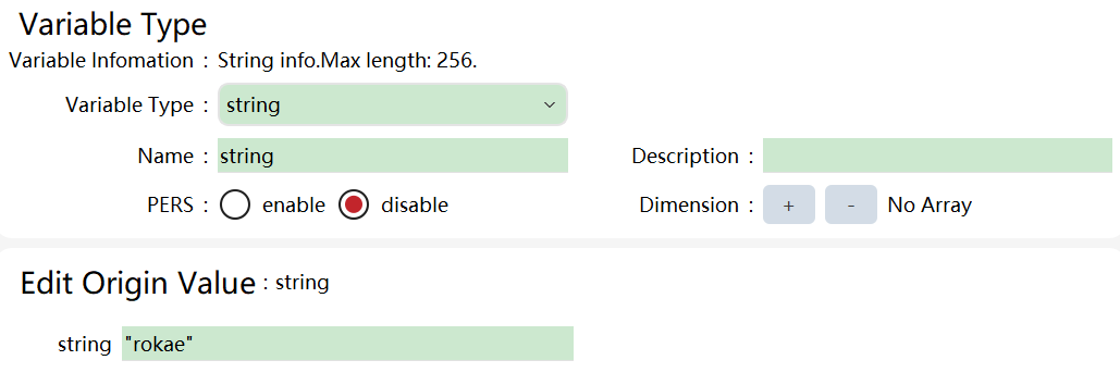
In the variable list:
It indicates that a string variable name is defined and initialized to "rokae". String type variables support the "+" operation for string concatenation, which can achieve string concatenation. Example: name = “Rok” + “ae” It means that the variable name is assigned to "Rokae". |
15.1.5 Array
Explanation |
An array is a collection of variables of the same type, either one-dimensional or multi-dimensional. The elements in the array are accessed using subscripts. The subscript of each dimension begins with 1. The total length of the array should not exceed 1000. |
Example |
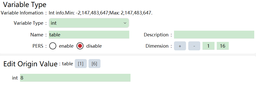
In the variable list:
It indicates that a two-dimensional array that contains 16 integer variables is defined. The value of the sixth element of line 1 is assigned to 8. |
15.1.6 byte
Explanation |
byte represents the unsigned byte in RL language, same as unsigned char in C++. The value range is 0−255, and negative values are not allowed. It is generally used in SocketSendByte instruction. When the byte variable’s value exceeds 255, it is automatically truncated, keeping only the lower 8 bits of the value, e.g. var byte data2=288, and the value of data2 is 32 after truncation. |
Example |
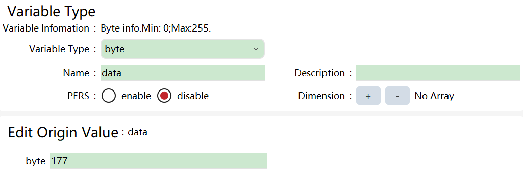
In the variable list:
It defines a byte variable data, which has a value of 177. |
15.1.7 clock
Explanation |
The clock is used for timing, and clock-related commands are just like a stopwatch used for timing. The time accuracy of clock type storage is 0.001s, and the maximum time interval is 45 days (i.e., 45 x 24 x 3600 seconds). |
Example |
In the variable list:
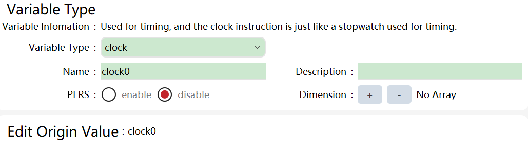
The following example shows how to use variable clock: Example 1: ClkStart (clock1); ClkStop (clock1); interval=ClkRead(clock1); ClkReset (clock1); Interval (pre-declared double variable) reads the interval between ClkStart and ClkStop, in seconds (s). |
15.1.8 Implicit type conversion
Explanation |
Currently, during data setup in the variable lists, data types are restricted. Values that do not match the variable type cannot be successfully entered, thus avoiding implicit type conversion. |
Example |
When defining the integer counter in the variable list, no decimals, only integers, can be entered. |
15.1.9 Confdata
Explanation |
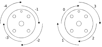
The confdata (Robot Configuration Data) is used to define the morphological configuration data that corresponds to the spatial target point. Since the robot mostly uses a rotary joint, any one of the joints exhibits the same status at 1° and 361°. Therefore, after the form of robot is selected, other measures are required to deal with the multiple-loop problem of the joint. For example, when the joint angle is between 0° and 90°, the quadrant number is 0. When the joint angle is between 90° and 180°, it is marked as 1 and is increased/decreased by 1 for every 90°. When the angle is negative, the corresponding number of quadrants is also negative, as shown in the following figure (left: negative joint angle; right: positive joint angle). For robot joints, the angle increases when rotating anticlockwise and decreases when rotating clockwise. In the figure below, the joint angle decreases as the joint rotates clockwise, and the corresponding confdata changes as -1->-2->-3->-4 and 3->2->1->0, respectively. For the xMate CR and SR collaborative robots, we directly record the rounded-down values of each joint angle in confdata. In addition, the same Cartesian space target point corresponds to different inverse kinematics, so it is necessary to use confdata to specify the form to be selected.
|
Definition |
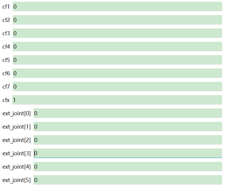
7 parameters are needed to complete the confdata, including: cf1, data type: int, the quadrant that corresponds to the Axis 1 angle or the rounded-down joint angle. cf2, data type: int, the quadrant that corresponds to the Axis 2 angle or the rounded-down joint angle. cf3, data type: int, the quadrant that corresponds to the Axis 3 angle or the rounded-down joint angle. cf4, data type: int, the quadrant that corresponds to the Axis 4 angle or the rounded-down joint angle. cf5, data type: int, the quadrant that corresponds to the Axis 5 angle or the rounded-down joint angle. cf6, data type: int, the quadrant that corresponds to the Axis 6 angle or the rounded-down joint angle. cf7, data type: int, the quadrant that corresponds to the Axis 7 angle or the rounded-down joint angle. cfx, data type: int, the configuration number of the form used by the robot, ranging from 0 to 8. |
Example |
There are different inverse kinematics for the same end-effector Cartesian space pose. The values of cfx from 0 to 8 represent each group of inverse kinematic solutions, which are explained in detail as follows. |
For 6-axis industrial robots, xMateER collaborative robots, and 7-axis robots:
cfx |
Wrist center is on Axis 1… |
Wrist center on the lower arm… |
Wrist angle is… |
0 |
Front |
Front |
Positive |
1 |
Front |
Front |
Negative |
2 |
Front |
Rear |
Positive |
3 |
Front |
Rear |
Negative |
4 |
Rear |
Front |
Positive |
5 |
Rear |
Front |
Negative |
6 |
Rear |
Rear |
Positive |
7 |
Rear |
Rear |
Negative |
For xMateCR collaborative robots (cfx=0 represents the solution that is closer to the joint angle represented by cf1−6):
cfx |
Wrist center is on Axis 1… |
Wrist center on the lower arm… |
Axis 5 angle is… |
0 |
|||
1 |
Front |
Front |
Negative |
2 |
Front |
Front |
Positive |
3 |
Front |
Rear |
Negative |
4 |
Front |
Rear |
Positive |
5 |
Rear |
Front |
Negative |
6 |
Rear |
Front |
Positive |
7 |
Rear |
Rear |
Negative |
8 |
Rear |
Rear |
Positive |
For xMateSR collaborative robots, cfx is always 0, indicating the solution that is closer to the joint angle represented by cf1−6.
For 3-axis industrial robots and 4-axis industrial robots:
cfx |
Wrist center on the lower arm… |
0 |
Front |
1 |
Rear |
15.1.10 jointtarget
Explanation |
To store the robot’s joint angle and the positions of external axes. |
Definition |
robax, Robot Axis, data type: double, containing 7 members of double type, which store the angle of the robot’s 7 joints, in Degree. extax, External Axis, data type: double, containing 6 members of double type, which can store the position of up to 6 external axes. If the external axis is a rotation axis, the unit is Degree; if the external axis is a linear axis, the unit is mm. |
Example |
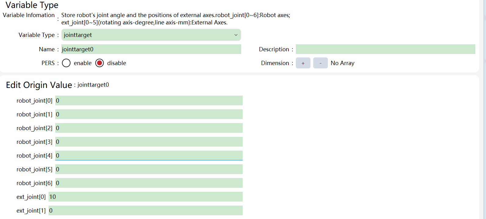
In the variable list:
The above command defines a point named "jointtarget0" in the joint space. Except that the Axis 6 is 90 degrees, the other axes of the robot are all 0 degrees. The first external axis is set to 10 degrees or 10 mm, depending on the type of external axis; the remaining external axes are set to zero. |
Structure assignment |
jointtarget j1 = J:{-268.649031, 321.536626, 259.344893, 55.143011, 66.111070, 169.543340, 29.916387}{EJ 0, 0, 0, 0, 0, 0}; Note:
|
15.1.11 load
Explanation |
The variable type load is used to store the dynamic parameters of the robot’s load. There are two main types of robot loads:
The variable load does not support individual creation. It can only be manually modified in the tool calibration interface as a member of the tool-type variables or automatically modified by the control system using the load identification function. By defining the dynamic parameters of the load correctly, the robot can achieve optimal performance. The wrong definition may lead to the following consequences:
|
Definition |
In the xCore system, the load is treated as a rigid body. There are four parameters for describing the load: mass, data type: double, the mass of the load, in kg. cogx, the offset of the center of mass in the X-direction, data type: double, if the tool is mounted on the robot, cogx records the offset of the center of mass in the X direction of the tool frame; if the external tool function is used, the cogx records the offset of the center of mass of the load held by the gripper in the X direction of the work object frame. cogy, the offset of the center of mass in the Y-direction, data type: double, if the tool is mounted on the robot, cogy records the offset of the center of mass in the Y direction of the tool frame; if the external tool function is used, the cogy records the offset of the center of mass of the load held by the gripper in the Y direction of the work object frame. cogz, the offset of the center of mass in the Z-direction, data type: double, if the tool is mounted on the robot, cogz records the offset of the center of mass in the Z direction of the tool frame; if the external tool function is used, the cogz records the offset of the center of mass of the load held by the gripper in the Z direction of the work object frame. q1~q4, quaternions, to record the direction of the principal axis of inertia of the load, data type: double; When the tool is mounted on the robot, the orientation of the principal axis of inertia is described in the tool frame. See the figure below for details:
When using an external tool, the direction of the principal axis of inertia is described in the work object frame. See the figure below:
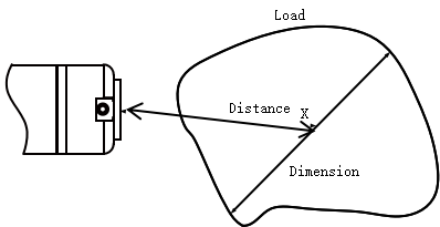
Ix, inertia x, data type: double, the inertia of the load along the x-axis, in kgm2. Iy, inertia y, data type: double, the inertia of the load along the y-axis, in kgm2. Iz, inertia z, data type: double, the inertia of the load along the z-axis, in kgm2. Note: Correctly defining the load inertia helps to improve the robot’s movement accuracy, especially when handling large objects. If ix, iy, iz are set to zero, the load will be treated as a mass. Usually, if the distance from the center of mass of the load to the flange center point is smaller than the maximum size of the load itself, the load inertia should be defined, as shown in the following figure:
|


15.1.12 orient
Explanation |
It is used to store the orientation information of the frame or space rigid body. Variables of orient type do not support individual creation or modification and are only used as member variables of some variables. |
Definition |
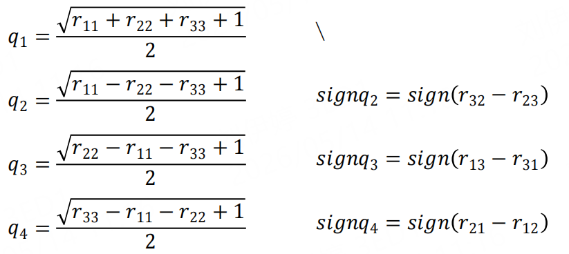
The RL language system uses quaternions to represent orientations, so there are a total of 4 components expressed as follows: q1, data type: double, the 1st component of the quaternion. q2, data type: double, the 2nd component of the quaternion. q3, data type: double, the 3rd component of the quaternion. q4, data type: double, the 4th component of the quaternion. |
Remarks |
We usually describe the orientation of the rigid body by using the rotation matrix. The quaternion is another way to describe orientation more concisely. The four components of the quaternion satisfy the following relationship:\(q_{1}^{2} + q_{2}^{2} + q_{3}^{2} + q_{4}^{2} = 1\) The rotation matrix and the quaternion can be converted to one another. It is supposed that there is a rotation matrix R,
\$R = \begin{bmatrix}
r_{11} & r_{12} & r_{13} \\$
\$r_{21} & r_{22} & r_{23} \\$
\$r_{31} & r_{32} & r_{33}
\end{bmatrix}\$
then:
|
15.1.13 pos
Explanation |
It is used to store location information in 3D space. Variables of pos type do not support individual creation or modification and are only used as member variables of some variables. |
Definition |
The RL language system describes three-dimensional space using the Cartesian frame, so the pos variable has three components: x, y, and z. X, data type: double, the X coordinate of the position. Y, data type: double, the Y coordinate of the position. Z, data type: double, the Z coordinate of the position. |
15.1.14 pose
Explanation |
It is used to store the position and orientation of Cartesian space. |
Definition |
X, data type: double, the X coordinate of the position. Y, data type: double, the Y coordinate of the position. Z, data type: double, the Z coordinate of the position. Q1, data type: double, the 1st component of the quaternion. Q2, data type: double, the 2nd component of the quaternion. Q3, data type: double, the 3rd component of the quaternion. Q4, data type: double, the 4th component of the quaternion. |
Structure assignment |
pose pose_obj = PE:{{X, Y, Z}, {Q1, Q2, Q3, Q4}}; Refer to the above definitions for parameter meanings. Example: pose pose_obj = PE:{{100, 100, 100}, {1, 0, 0, 0}}; This struct supports the assignment of Euler angles. Please refer to the description of the robtarget structure for details. |
15.1.15 robtarget
Explanation |
It aims to store Cartesian positions and orientations of 3D space, which is used for MoveJ, MoveL, MoveC, and MoveT commands. Because of the multi-solvability of the inverse kinematics of the robot, the robot can arrive in many different forms for the same target pose. In order to specify the configuration form, the robtarget variable also contains the robot configuration data. Variables of the robtarget type are automatically created when the motion command is inserted by auxiliary programming. Manually changing the internal value of the variable may lead to non-correspondence between the Pose and ConfData, and the robot cannot execute the motion command normally. Note: The use of Cartesian positions and orientations in robot programs is defined in the work object frame. If the work object used in the end is not the same as that used during the initial programming, the robot’s motion will deviate from the desired path. Therefore, it shall be confirmed that the changes in work object will not cause danger in the following two cases:
Improper use can result in personal injury or equipment damage! |
Definition |
Trans, spatial position, data type: pos, the position offset stored in the reference frame. Rot, orientation, data type: orient, the orientation stored in the reference frame. Conf, Robot Configuration Data, data type: confdata, to save the configuration data of the robot. Please refer to confdata for details. Extax, External Axis, data type: double, containing 6 members of double type, which can store the position of up to 6 external axes. If the external axis is a rotation axis, the unit is Degree; if the external axis is a linear axis, the unit is mm. |
Example |
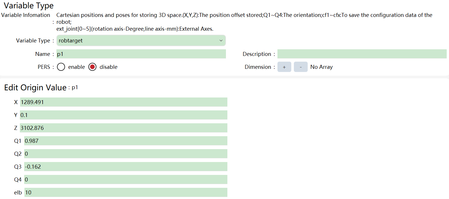
A Cartesian space pose named p1 with the position and orientation (in quaternions) as shown above is defined. The elbow is 10°, and the angles of the Axis 1, 3, 5, and 7 are between 0 and 90°. The robot belongs to the first group of morphological configurations (see confdata for details), and all external axes are in zero. |
Structure assignment |
robtarget rob1 = p:{{849.572593, -347.654631, 35.341636}, {-0.361604, 0.078279, 0.640346, -0.673106}, -1.058584}{cfg 1, 2, 3, 4, 5, 6, 7, 8}{EJ 1, 2, 3, 4, 5, 6}; Explanation: p:{{Space Position Trans}, {Orientation Rot}, {Arm Angle}}{cfg: Robot Configuration Data Conf}{EJ: External Axis Information Extax}; Starting from version 3.2, the robtarget type supports direct assignment of Euler angles (i.e., A, B, C). In version 3.1 and earlier, it only supports quaternions (q1−q4) to set the rotation orientation. Example code (pseudocode): proc main() robtarget p1; //Version 3.1 and earlier: only support quaternion assignment p1.rot.q1 = 1; p1.rot.q2 = 0; p1.rot.q3 = 0; p1.rot.q4 = 0; //Added in version 3.2: support Euler angle assignment p1.rot.a = someVariable; //Variable p1.rot.b = 90.0; //Constant p1.rot.c = reg1; //Register //Note: The data types of a, b, and c are double endproc |
Attention |
Euler angle is in degrees (°) When assigning to Euler angles, the assignment source can be a variable, constant, or register, as long as its value can be implicitly converted to a double type. A robtarget maintains two sets of representations — Euler angles (A/B/C) and quaternions (q1−q4) internally. Whenever either representation is modified, the other one will be automatically synchronized and updated (provided that the data is valid). Quaternion validity handling rules: Quaternions must satisfy the normalization condition (the sum of squares is 1). After a single assignment, the system will perform a check: After the assignment of each component (q1, q2, q3, or q4), the system will check whether the current quaternion is valid: If valid: The corresponding Euler angles (A/B/C) will be updated synchronously. If invalid: The Euler angles will not be updated and will retain their previous values. If the quaternion remains invalid after an overall assignment: Even after assigning all quaternion components, if the final quaternion still does not satisfy the normalization condition, the Euler angles will remain unchanged. In such cases, the system will perform a validity check when executing motion commands, and may either report errors or automatically normalize the quaternion (the specific behavior is determined by the motion command execution). Explanation of Euler angle assignment behavior: When assigning any component of a, b, or c, the system will immediately recalculate the corresponding quaternion based on the current complete Euler angle value and update rot. q1−q4. The Euler angles derived from the quaternion will not override the Euler angle values explicitly set by the user. The original Euler angle values are also kept. This is because the two representations are mathematically equivalent, making redundant updates unnecessary. |
15.1.16 signalxx
Explanation |
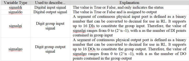
signalxx type variables are used to describe I/O signals. All signalxx type variables need to be defined in the "Input/Output" and then used in the program. Direct declaration in the program is not supported. signalxx currently only supports digital input and output, including the following variable types:
The signaldo and signalgo types contain only signal references and can be assigned using separate commands (e.g., SetDO, SetGO, etc.). signaldi and signalgi can be used to directly obtain the value of the corresponding input signal in the program. Note:
|
Example |
Example 1 //Use the state of the digital input as a criterion for judgment IF (di1 == true) do something… ENDIF Example 2 //Use the state of the digital input as a criterion for judgment. For example, if the definition group input gi2 maps the first three bits of the 1st byte of Profinet IO, then when the values of bit0 to bit2 are 0, 1, and 1, the value of gi2 is 110 (6 after being converted to int). The same goes for group output (signalgo) as well. IF (gi2 == 6) do something… endif |
15.1.17 speed
Explanation |
It is used to define the speed of the robot and the external axes. |
Definition |
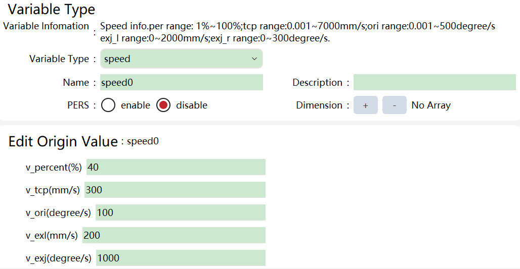
The speed-type variable contains 5 member variables: Joint Velocity Percentage, TCP Linear Velocity, Orientation Velocity, External Axis Linear Velocity, and External Axis Angular Velocity. |
Example |
In the variable list: |
Structure assignment |
speed speed0 = v:{40, 300, 100, 1000, 200}; |
Name |
Joint Velocity Percentage |
TCP Linear Velocity |
Orientation Velocity |
External Axis Angular Velocity |
External Axis Linear Velocity |
v5 |
1% |
5 mm/s |
200°/s |
5°/s |
2 mm/s |
v10 |
3% |
10 mm/s |
200°/s |
10°/s |
5 mm/s |
v25 |
5% |
25 mm/s |
200°/s |
25°/s |
12 mm/s |
v30 |
5% |
30 mm/s |
200°/s |
30°/s |
15 mm/s |
v40 |
5% |
40 mm/s |
200°/s |
40°/s |
20 mm/s |
v50 |
8% |
50 mm/s |
200°/s |
50°/s |
25 mm/s |
v60 |
8% |
60 mm/s |
200°/s |
60°/s |
30 mm/s |
v80 |
8% |
80 mm/s |
200°/s |
80°/s |
40 mm/s |
v100 |
10% |
100 mm/s |
200°/s |
100°/s |
50 mm/s |
v150 |
15% |
150 mm/s |
200°/s |
150°/s |
75 mm/s |
v200 |
20% |
200 mm/s |
200°/s |
200°/s |
100 mm/s |
v300 |
30% |
300 mm/s |
200°/s |
300°/s |
150 mm/s |
v400 |
40% |
400 mm/s |
200°/s |
400°/s |
200 mm/s |
v500 |
50% |
500 mm/s |
200°/s |
500°/s |
250 mm/s |
v600 |
60% |
600 mm/s |
200°/s |
600°/s |
300 mm/s |
v800 |
70% |
800 mm/s |
200°/s |
800°/s |
400 mm/s |
v1000 |
100% |
1000 mm/s |
200°/s |
1000°/s |
500 mm/s |
v1500 |
100% |
1500 mm/s |
200°/s |
1500°/s |
750 mm/s |
v2000 |
100% |
2000 mm/s |
200°/s |
2000°/s |
1000 mm/s |
V3000 |
100% |
3000 mm/s |
200°/s |
3000°/s |
1000 mm/s |
v4000 |
100% |
4000 mm/s |
200°/s |
4000°/s |
1000 mm/s |
vmax |
100% |
- |
- |
- |
The system predefines some common speed variables, as shown in the following table.
|
All space rotation speeds in the system’s pre-defined speed variable are 200°/s. If there are special requirements on the rotation speed of the end-effector of the robot, a new speed variable can be defined for use according to the process requirements. vmax is the only predefined parameter that can be configured by the user, and the modification method is described in 8.4.6. |
15.1.18 tool
Explanation |
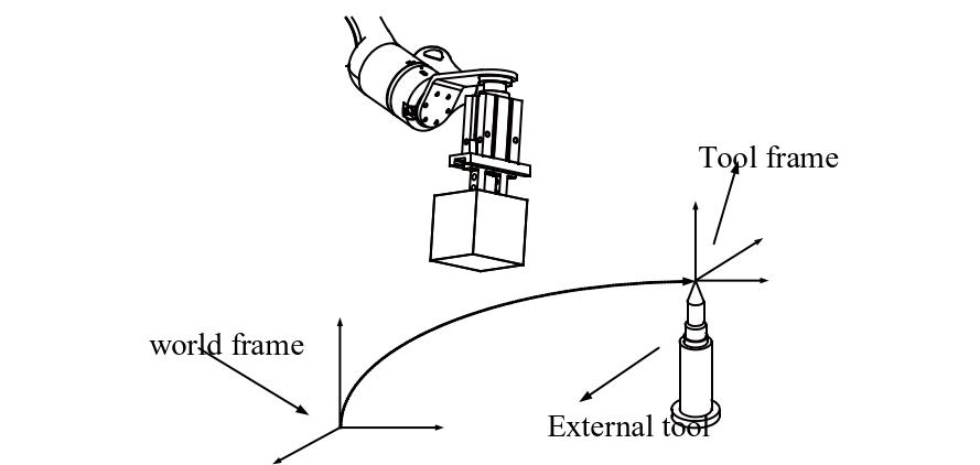
The tool-type variables are used to record tool parameters, including TCP, orientation, and dynamic parameters of the tools used by the robot. The robot uses tools to interact with the outside world, so the tool variable will affect the motion of the robot from the following aspects: Only the TCP will move according to the programmed path and speed. When the robot executes a pure spatial rotation, only TCP will remain motionless; The motion path and speed specified during programming refer to the path and speed of the tool frame relative to the work object frame. Therefore, replacing a well-calibrated tool or work object does not affect the shape and speed of the path; When using external tools, the speed of programming refers to the speed of a work object (relative to external tools). Note that when using the external tool, tframe in the tool-type variable will record the zero position and orientation offset of the external tool, while tload will record the dynamic parameters of the gripper that is installed at the end-effector of the robot for grasping work object. The data of the tool-type variable is stored in the database. When the program is loaded, it is read by the program editor from the database. Therefore, do not try to modify the tool-type variable directly in the program editor, and thus the unpredictable errors will be avoided. If you need to modify the tool-type variable, please modify it through the calibration interface. See the Calibration of the tool frame for details. Be sure to correctly define the dynamic parameters of the end-effector load of the robot, including the tool itself and the two parts of the object captured by the tool. The wrong definition may lead to the following consequences:
Overloading of mechanical components results in a reduction in life or damage. |
Example |
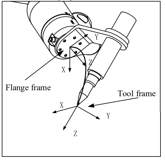
Robhold, data type: boot, to define whether the tool is installed on the robot. True indicates that the tool is installed on the robot. False indicates that the tool is not installed on the robot and an external tool is being used. When making a jog or executing a program, only one of the robhold parameters can be True in the tool/work object combination used at the same time. That is, if the robhold of the tool is True, the corresponding work object robhold must be false, and vice versa; otherwise, the robot will prompt an error, and it is impossible to make a jog or execute the corresponding program command. Tframe, Tool Frame, data type: pose, to record the tool frame of the tool used, including: TCP represents the offset in the x, y, and z directions relative to the robot end-effector flange frame, in millimeters. The orientation offset of the tool frame relative to the flange frame is expressed in quaternion. See the following figure for details:
Tload, dynamic parameters of the tool, data type: load, to record the dynamic parameters of the tool. For the common tool, tload describes the dynamic parameters of the entire tool. For external tools, tload describes the dynamic parameters of the gripper used by the robot (holding the work object). For general tools installed on the robot, the load parameters include: The mass of the tool (weight), in kg; The center of gravity of the tool, described in the flange frame, in millimeters (mm); the direction of the principal axis of inertia, described in the flange frame; and The inertia magnitude of the tool along the principal axis of inertia, in kgm2. If all inertia components are defined as 0 kgm2, the tool is treated as a Point Mass. Note: When using the external tool function, the TCP and orientation are defined relative to the world frame. If the robot is using an external tool, then the tload member is used to record the dynamic parameters of the gripper installed on the robot. The meaning of the specific parameters remains unchanged. Please note that the tload members only define the dynamic parameters of the gripper used by the robot (holding the work object). The dynamic parameters of the gripped work object are not included. To ensure that the robot performs optimally under all circumstances, you need to define two tool variables to handle this situation:
The use of different tools in the motion command would help implement the switching function with or without load. |
Structure assignment |
tool tool0 = {whether the tool is handheld, {{tool position}, {tool orientation quaternion}}, {mass, {center of gravity X, center of gravity Y, center of gravity Z}, {load orientation quaternion}, inertia ix, inertia iy, inertia iz}}; whether the tool is handheld: true, handheld; false, external. tool tool0 = {Example:true, {{0, 0, 0}, {1, 0, 0, 0}}, {0, {0, 0, 0}, {1, 0, 0, 0}, 0, 0, 0}}; This struct supports the assignment of load Euler angles. Please refer to the description of the robtarget structure for details. |
15.1.19 Trigdata
Explanation |
trigdata is used to store information data about the trigger events during robot motion, including trigger conditions and trigger actions. The trigger condition is usually reaching a specified location on the path; the trigger action can be setting IO, setting variables, etc. Variables of type trigdata cannot be defined by the assignment operator and can only be defined by a specific RL command, so the information stored in each trigdata variable depends on the Trig command as used, for example, the TrigIO, etc. Then, it can be used by the corresponding movement commands TrigL, TrigC, TrigJ, etc. |
Example |
The following example shows how to use the trigdata: Example 1 VAR trigdata gripopen; TrigIO(gripopen, 0.5, do1, true); TrigL(p1,v500, gripopen, fine, tool1); |
15.1.20 wobj
Explanation |
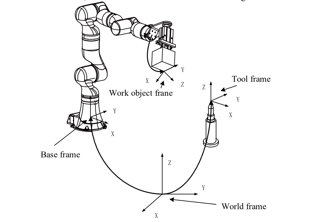
wobj is an abbreviation for Work Object. Work object refers to an object processed, handled, or transported by a robot. All the positions used in the motion command are defined in the work object frame (if no work object frame is specified, it defaults to the world frame. The world frame can be seen as a wobj0). There are several benefits in doing this:
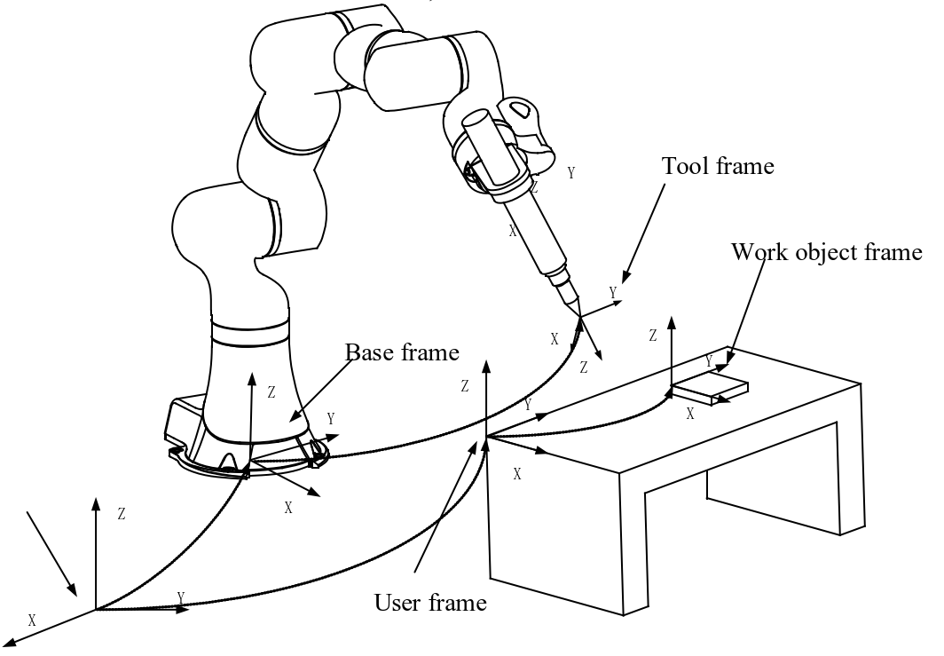
Under normal circumstances, if you do not define a specific work object frame, the control system will then regard the world frame as the default work object frame wobj0. However, when using external tools, the work object frame must be defined because the programming path and speed refer to the path and speed of the work object, rather than the tool. Usually, the work object frame is defined relative to the user frame, but if the user does not specify a user frame, the work object frame is defined by default relative to the world frame. For details, see the Robot’s frames. The work object actually consists of two frames, the user frame and the work object frame. Inserting a user frame at the upper layer of the work object frame is to support the situation where multiple identical work objects need to be machined. For an explanation of the defining relationships of the relevant coordinates, see the explanation of oframe in the "Definitions" section. |
Definition |
Robhold, to define whether the work object is mounted on the robot. True indicates that the work object is mounted on the robot and the external tool is currently being used. False indicates that the work object is not mounted on the robot and the normal tool is currently being used. Ufprog, User Frame Programmed, data type: bool, to define whether the user frame is fixed or moving. True indicates that the user frame is fixed, False indicates that the user frame is moving, e.g., to define whether it is on an external positioner or another robot. This value is mostly used when the robot is required to coordinate its movement with the positioner or other robots. Ufmec, User Frame Mechanical Unit, data type: string, the mechanical unit name is used to specify which mechanical unit the user frame is bound to; it is useful only if ufprog is false. Oframe, Work Object Frame, data type: pose, to store the origin and orientation of the work object frame. uframe_id, User Frame ID, data type: int, to store the id of the user frame. The corresponding user frame can be found by id. When using normal tools (non-external tools), the frame definition chain is as follows: The work object frame is defined relative to the user frame; the user frame is defined relative to the world frame.
When using external tools, the frame definition chain is as follows: The work object frame is defined relative to the user frame; the user frame is defined relative to the flange frame.
|
Structure assignment |
wobj wobj0 = {Robhold, Ufprog, Ufmec, Oframe, uframe_id, { mass, {center of gravity X, center of gravity Y, center of gravity Z}, {load orientation quaternion}, inertia ix, inertia iy, inertia iz }}; Refer to the "Definition" section of this table for parameter meanings. wobjExample: wobj0 = {false, true, "robot", {0, 0, 0}, {1, 0, 0, 0}, 0, {0, {0, 0, 0}, {1, 0, 0, 0}, 0, 0, 0}}; This struct supports the assignment of load Euler angles. Please refer to the description of the robtarget structure for details. |
15.1.21 zone
Explanation |
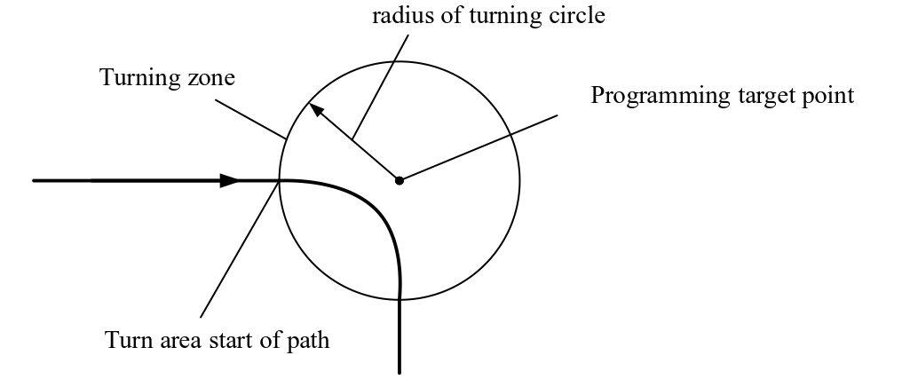
The zone variable is used to define how a certain motion ends, or to define the size of the turning zone between two motion trajectories. For the same target point of robot commands, there are two processing methods in the motion command:
The size of the turning zone cannot exceed half of the path length. If it is exceeded, the system will automatically reduce the turning zone to half the total path length. The use of turning zones prevents the robot from starting and stopping frequently, significantly reducing the cycle time. Note: In some special cases, the turning zone will be canceled. The system will report the log "Corner Path Failed". Possible causes are as follows
|
Definition |
Joint space trajectories and Cartesian space trajectories define turning zones with different parameters. The variable contains two parts: distance and percent. Distance, size of turning zone in Cartesian space, data type: double; it is used for the commands MoveL, MoveC, and MoveT to define the size of the turning zone for Cartesian space trajectories, that is, when the robot moves to a point with a distance of several millimeters to the target point, it starts to move to the next target point, in millimeters, with the value ranging from 0 to 200 mm. Percent, turning percentage, data type: double; it is used for MoveJ and MoveAbsJ, indicating how far it is to the target angle when starting turning. 100% represents half the value of the entire rotation angle. For command MoveL with pure space-rotation, the parameter Percent is used instead of Distance. |
Example |
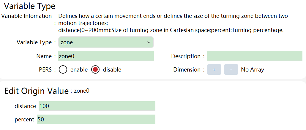
In the variable list:
A zone variable is defined, in which the size of the Cartesian turning zone is 100 mm and the size of the joint space turning zone is 50%. |
Structure assignment |
zone z1 = s:{Distance, Percent}; Refer to the "Definition" section of this table for parameter meanings. zone z1 = Example:s:{1, 1}; |
The system predefines some common turning zone variables, as shown in the following table.
Name |
Size of turning zone in Cartesian space |
Turning percentage |
fine |
0 mm |
0% |
z0 |
0.005 mm |
0.0005% |
z1 |
1 mm |
1% |
z5 |
5 mm |
3% |
z10 |
10 mm |
5% |
z15 |
15 mm |
8% |
z20 |
20 mm |
10% |
z30 |
30 mm |
15% |
z40 |
40 mm |
20% |
z50 |
50 mm |
25% |
z60 |
60 mm |
30% |
z80 |
80 mm |
40% |
z100 |
100 mm |
50% |
z150 |
150 mm |
75% |
z200 |
200 mm |
100% |
15.1.22 torqueinfo
Explanation |
It is used to describe the forces and torques applied to the robot; It includes joint space torque information and Cartesian space torque information; |
Definition |
joint_torque, data type: joint space torque information; cart_torque, data type: Cartesian space torque information; joint_torque.measure_torque, data type: double array, information of measured force in the joint space and the torque applied to each axis measured by the force sensor; joint_torque.external_torque, data type: double array, information of external force in the joint space, and information of the torque applied to each axis measured by the controller based on the robot model and measured force; cart_torque.m_force, data type: double array, force in all directions (xyz) in the Cartesian space; cart_torque.m_torque, data type: double array, torque in all directions (xyz) in the Cartesian space; |
Example |
The following example shows how to use variable torqueinfo: Example 1 TorqueInfo tmp_info = GetEndtoolTorque(tool1, wobj1); //Obtain the information architecture of the torque applied to the tool at the end-effector of the robot in the case of tool1 wobj1 … print(tmp_info.joint_torque.measure_torque); print(tmp_info.joint_torque.external_torque); //Print the measured force and external force of each axis … print(tmp_info.cart_torque.m_torque); //Print Cartesian space torque … print(tmp_info.cart_torque.m_force); print(tmp_info.cart_torque.m_torque); //Print information of force and torque in X direction |
15.1.23 SocketServer
Explanation |
A Socket TCP server is established on the controller to listen for connections initiated by external devices as the client. This server is only used to listen for connection requests and multiple connections are supported. When a connection is established, a new SocketConn object is generated for communication. Note:
|
Definition |
Ip, data type: string; the control system uses the ip parameter to match the network interface controller (NIC) and uses the corresponding NIC for network listening. If this parameter is set to "0.0.0.0", it means listening for the connections of all NICs. In most cases, it can be set to "0.0.0.0". Port, data type: int, listening port. When an external client initiates a connection, specify the value of the server port set for this purpose. Name, data type: string, the unique identifier of the server used in the RL program. It is unique within the project and can be shared between multiple tasks without naming conflicts. |
Example |
Example 1 SocketServer ss = {"192.168.0.160", 8090, "svr"}; //Only listen for NIC with ip set to 192.168.0.160 SocketConn conn = SocketAccept( "svr"); Example 2 SocketServer ss = {"0.0.0.0", 8090, "svr"} ; //Listen for all NICs of the robot SocketConn conn = SocketAccept( "svr"); |
15.1.24 SocketConn
Explanation |
Socket TCP connection object, used for communication to external devices. There are two types:
|
Definition |
Ip, data type: string; when the robot is used as a client, this parameter indicates the ip of the external device’s server. When the robot is used as a server, this parameter indicates the ip of the external client when a connection is established by the external device. Port, data type: int, listening port. When the robot initiates a connection, the server port of the external device should be specified. Name, data type: string, the unique identifier of the connection used in the RL program. It is unique within the project and can be shared between multiple tasks among connections and between connection and server. Server names should not conflict within the project. Cache, data type: int, size of the cache, indicating max data received that can be cached; it can be left blank. 1 by default. Suffix, data type: string, terminator, indicating the end of a message; it can be left blank. "+r" by default. Attr, data type: string, connection attribute.
State, data type: string, current communication connection status; closed: connection closed; established: connection established and working properly. Note:
|
Example |
Example 1 //Server ip "192.168.0.202", port 8090, connection name "clt", cache default to 1, and suffix default to "+r" SocketConn scnn1 = {"192.168.0.202", 8090, "clt"}; Example 2 //Server ip "192.168.0.203", port 8091, connection name "clt1", cache 2, and suffix default to "+r" SocketConn scnn2 = {"192.168.0.203", 8091, "clt1", 2}; Example 3 //Server ip "192.168.0.204", port 8092, connection name "clt2", cache 2, and suffix "+n" SocketConn scnn3 = {"192.168.0.204", 8092, "clt2", 2, "+n"}; Example 4 //Used as server, connection established by the external device //Server ip "192.168.0.204", port 8092, connection name "clt2", cache 2, and suffix "+n" SocketConn conn = SocketAccept( "svr1"); Print(conn.ip); //ip of the external device Print(conn.port); //Port of the external device to establish the connection Print(conn.cache); //Buffer queue for receiving messages Print(conn.suffix); //Sending and receiving suffix |
15.1.25 FCBoxVol
Explanation |
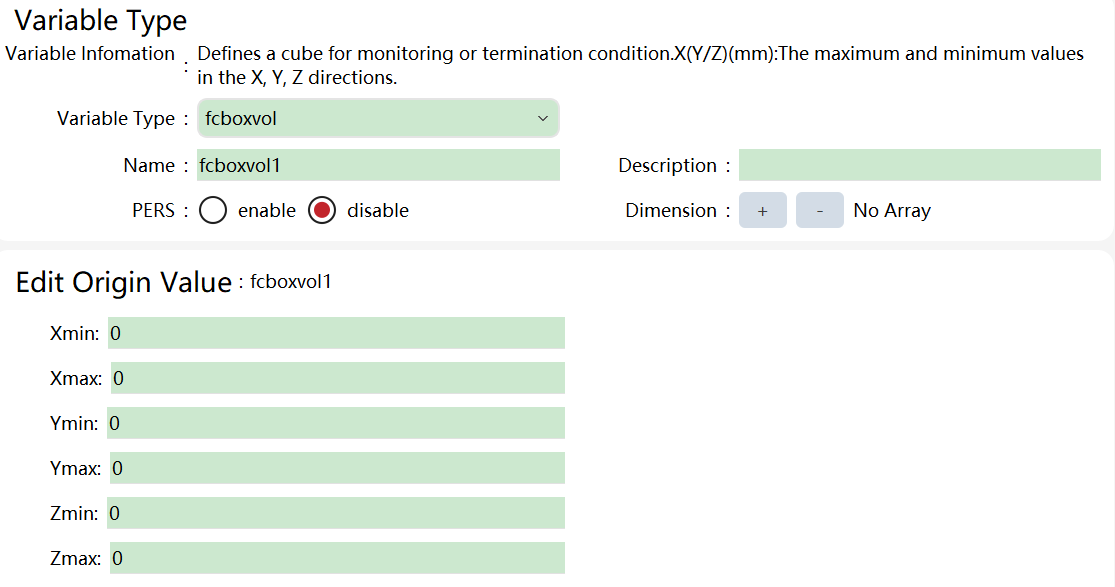
It is used to define a spatial cuboid for position monitoring or termination conditions after force control is enabled. |
Definition |
Xmax represents the coordinate value of the cuboid boundary in the positive x direction; Xmin represents the coordinate value of the cube boundary in the negative x direction; Ymax represents the coordinate value of the cuboid boundary in the positive y direction; Ymin represents the coordinate value of the cube boundary in the negative y direction; Zmax represents the coordinate value of the cuboid boundary in the positive z direction; Zmin represents the coordinate value of the cube boundary in the negative z direction; |
Example |
|
Structure assignment |
FcBoxVol fcboxvol0 = FCBV:{Xmin, Xmax, Ymin, Ymax, Zmin, Zmax}; Refer to the "Definition" section of this table for parameter meanings. Example: FcBoxVol fcboxvol0 = FCBV:{0, 1, 2, 3, 4, 5}; |
15.1.26 FCSphereVol
Explanation |
It is used to define a spatial sphere for position monitoring or termination conditions after force control is enabled. |
Definition |
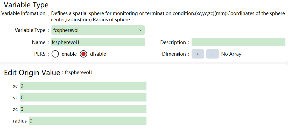
Xc: the coordinate value of the center of the spatial sphere in the x direction; Yc: the coordinate value of the center of the spatial sphere in the y direction; Zc: the coordinate value of the center of the spatial sphere in the Z direction; Radius: the spatial sphere radius; |
Example |
|
Structure assignment |
FcSphereVol fc = FCSV:{xc, yc, zc, radius}; Refer to the "Definition" section of this table for parameter meanings. FcSphereVolExample: fc = FCSV:{1, 2, 3, 4}; |