10.11.1 Overview
xMate CR, ER, and SR robots support end RS485 communication and are currently compatible with multiple electric grippers and suction cups. This interface is mainly used for configuring and testing adapted electric grippers and suction cups.
Note:
-
The function is only applicable to xMate ER, CR, and SR robots;
-
The old version of the robot’s end board may not be compatible with this function. Please contact the ROKAE to upgrade the board firmware;
-
Before using the xMate CR model, please confirm that the end parameters of the xPanel are configured correctly;
10.11.2 Configurations
On the HMI main interface, you can enter the Electric gripper and suction cup interface through the menu "Communication" -> "Electric gripper and suction cup", as shown in the following figure:
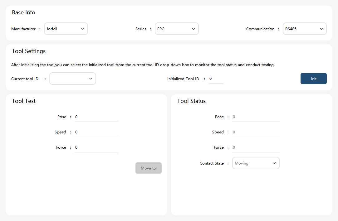
The parameter description for setting "Basic Information" is as follows:
| Parameter | Explanation |
|---|---|
Manufacturer |
Jodell, Robustmotion, Robotiq, and DH; |
Series |
Jodell, supports EPG series electric grippers and EVS series suction cups; |
Communication |
Only RS485 interface is supported; |
10.11.2.1 Jodell electric grippers
The "Basic Information" section allows the Manufacturer to select Jodell as the preferred option, while the Series option enables them to choose EPG. Consequently, the HMI will seamlessly transition to the testing interface of the EPG series electric gripper, as shown in the following figure:
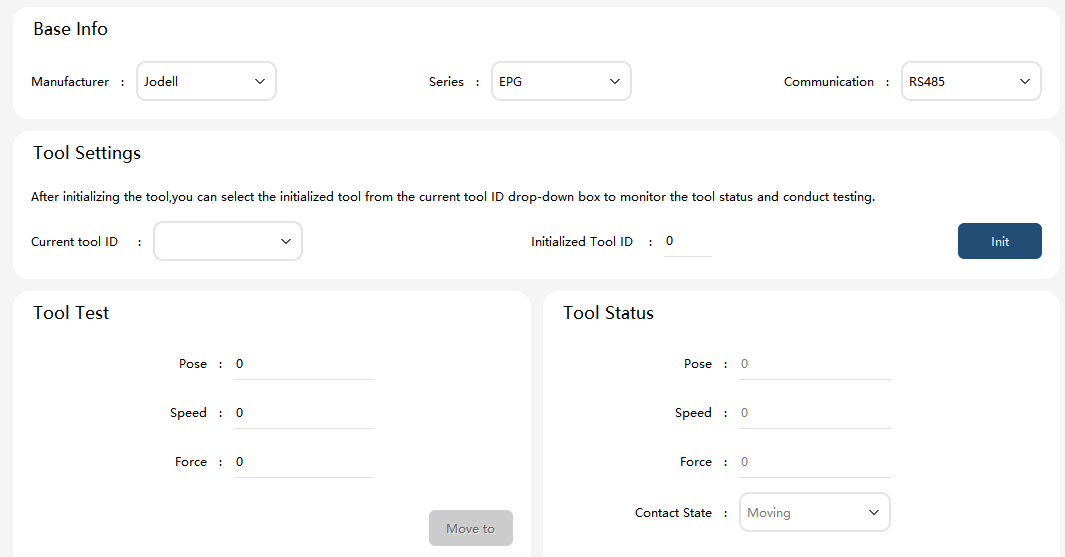
Initialization: To test an electric gripper, enter the ID of the gripper and click the "Initialize" button. If the gripper successfully detects and initializes, it indicates that the hardware connection and communication are functioning properly, allowing users to proceed or utilize it for further operations.
Tool testing: After initialization, click the "Move to" button to control the electric gripper’s movement to a specified position with designated velocity and force. If the gripper reaches the desired position or encounters objects with predetermined force, it will halt its motion accordingly while displaying its contact detection status on the testing interface.
The relevant parameter settings are explained as follows:
Parameter |
Value/Description |
Tool ID |
Enter the ID of the electric gripper. This ID is the electric gripper ID set in the Jodell Robotics debugging software |
Tool position |
Set the position of the electric gripper, with a range from 0 to 255 |
Tool velocity |
Set the velocity of the electric gripper, with a range from 0 to 255 |
Tool torque |
Set the torque of the electric gripper, with a range from 0 to 255 |
10.11.2.2 Jodell suction cup
The "Basic Information" section includes the selection of Jodell as the Manufacturer and EVS as the Series. Consequently, the HMI will automatically switch to the testing interface specifically designed for suction cups belonging to the EVS series, as shown in the following figure:
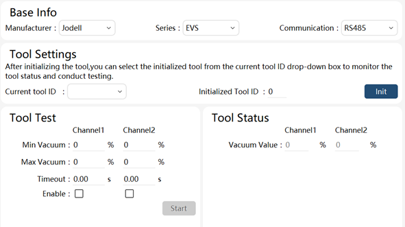
Initialization: To test a suction cup, first input the ID of the suction cup and click on the "Initialize" button. If the software prompts successful initialization, it indicates that the hardware connection and communication of the suction cup are functioning properly, allowing users to proceed to the next step or utilize it further.
Tool testing: After initialization, adjust the suction cup parameters as required. Once all parameters have been entered, click on the "Setup" button to conduct a test on the suction cup.
The parameter settings are explained as follows:
Parameter |
Value/Description |
Channel selection |
The suction cup supports two channels. The user can choose the effectiveness of the two channels at will |
Minimum vacuum |
Set the target vacuum level of the suction cup. The suction cup stops working when the inside vacuum level reaches this value |
Maximum Vacuum |
Set the target vacuum level of the suction cup. The suction cup starts working when the inside vacuum level is greater than this value |
Timeout period |
Times out when the minimum vacuum level specified is not reached in the specified time |
10.11.2.3 Robustmotion electric gripper
The Manufacturer selects Robustmotion in the "Basic Information" section, and chooses either RM-RGM or RM-C for the Series. As a result, the HMI will automatically switch to the test interface of the Robustmotion series electric gripper, as shown in the following figure:
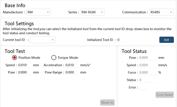
Initialization: To test an electric gripper, it is necessary to input the ID of the device and click on the "Initialization" button. If the electric gripper is properly configured and communication is established, initialization will be successful, enabling further testing and usage.
Current tool ID: This displays a list of initialized device IDs. By selecting a device with its corresponding ID, users can view its status and conduct tests.
Tool state: After successful initialization, the Robustmotion electric gripper can display various tool states including position (mm), speed (mm/s), torque (%), in-place state (1: in place), and error alarms (error code information).
Tool test: The running condition of Robustmotion electric grippers can be tested in position mode or torque mode. According to the manufacturer’s instructions, position mode should be used for testing grip release while torque mode should be used for grip closure.
Position mode: Parameters that can be set include absolute positioning position (mm), speed (mm/s), positioning range (considering in-place error range, mm), and acceleration (mm/s^2), as shown above.
Torque mode: The parameters that can be set include distance (relative distance, mm), speed (mm/s), force (%), acceleration (mm/s2), positioning range (in-place error range considered, mm), and time range; as shown below:
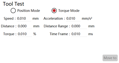
The electric gripper can move according to the set mode and parameters if clicking on the "Move to" button.
10.11.2.4 Robotiq 2F_85 electric gripper
In the "Basic Information", set the Manufacturer to Robotiq and the Series to 2F_85, and the HMI will switch to the testing interface of the Robotiq 2F_85 electric gripper, as shown in the following figure:
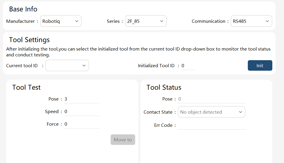
Initialization: To test an electric gripper, enter the ID of the gripper and click the "Initialize" button. If the gripper successfully detects and initializes, it indicates that the hardware connection and communication are functioning properly, allowing users to proceed or utilize it for further operations.
Tool testing: After initialization, click the "Move to" button to control the electric gripper’s movement to a specified position with designated velocity and force. If the gripper reaches the desired position or encounters objects with predetermined force, it will halt its motion accordingly while displaying its contact detection status on the testing interface.
The relevant parameter settings are explained as follows:
Parameter |
Value/Description |
Tool ID |
Enter the ID of the electric gripper |
Tool position |
Set the position of the electric gripper, with a range from 3 to 255 |
Tool velocity |
Set the velocity of the electric gripper, with a range from 0 to 255 |
Tool torque |
Set the torque of the electric gripper, with a range from 0 to 255 |
10.11.2.5 DH electric gripper
The "Basic Information" section allows the Manufacturer to select DH as the preferred option, while the Series option enables them to choose PGI. Consequently, the HMI will seamlessly transition to the testing interface of the PGI series electric gripper, as shown in the following figure:
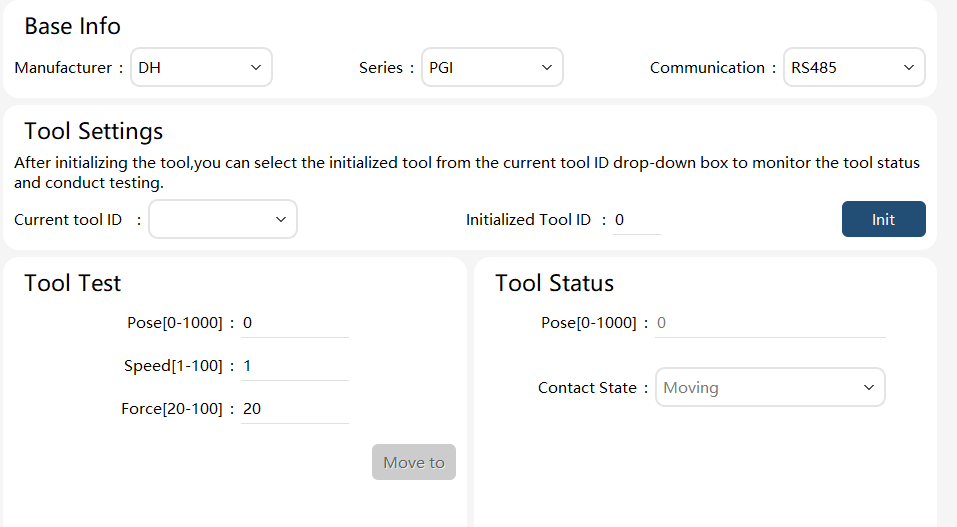
Initialization: To test an electric gripper, enter the ID of the gripper and click the "Initialize" button. If the gripper successfully detects and initializes accompanied by executing one opening and closing action, it indicates that the hardware connection and communication are functioning properly, allowing users to proceed or utilize it for further operations. Note: In the initialization process, the opening and closing of the electric gripper determines its operating range, and the electric gripper will move within the operating range.
Tool testing: After initialization, click the "Move to" button to control the electric gripper’s movement to a specified position with designated velocity and force. If the gripper reaches the desired position or encounters objects with predetermined force, it will halt its motion accordingly while displaying its contact detection status on the testing interface.
Note: If the electric gripper grasps an object during movement, it will not continue to move even if the object is removed, and will only move again after a new target position is re-set.
The electric gripper has five statuses, namely 0 (the electric gripper is moving), 1 (the electric gripper does not grasp the object), 2 (the electric gripper grasps the object), 3 (the object falls), and 4 (no content is displayed, that is, the current ID is not initialized successfully).
The relevant parameter settings are explained as follows:
Parameter |
Value/Description |
Tool ID |
Enter the ID of the electric gripper. This ID is the one set in the DH debugging software |
Tool position |
Set the position of the electric gripper, with a range from 0 to 1000 in % (determined in the initialization process) |
Tool velocity |
Set the speed of the electric gripper, with a range from 0 to 100 in % |
Tool torque |
Set the torque of the electric gripper, with a range from 20 to 100 in % |