10.5.1 Overview of bus devices
CC-Link, Modbus, EtherCAT, and PROFINET are supported.
CC-Link includes CC-Link devices (connected via EtherCAT) and CC-Link IE Field Basic.
EtherCAT can be used to expand bus modules such as IO modules, PROFINET, and EtherNet/IP.
Supported Bus |
Protocol |
Supported method |
Remarks |
Modbus |
TCP |
Master and slave |
|
UDP |
Not supported |
||
RTU |
Master and slave |
Industrial robots only |
|
CC-Link |
485 |
Remove device station (slave) |
Industrial robots only |
IE Field Basic |
Remove device station (slave) |
The following function codes are supported in Modbus:
Function code |
Meaning |
Supported |
0x01 |
Read coil |
Supported |
0x05 |
Write a single coil |
Supported |
0x0F |
Write multiple coils |
Supported |
0x02 |
Read discrete input |
Supported |
0x04 |
Read input register |
Not supported |
0x03 |
Read holding register |
Supported |
0x06 |
Write a single holding register |
Supported |
0x10 |
Write multiple holding registers |
Supported |
10.5.2 Bus devices parameter configuration
The page is at: "Communications" -> "Fieldbus Devices". The page is divided into two parts. The upper part manages all bus connections and allows for individual opening and closing operations for each bus connection. When the bus connection is closed, the IO configured for this connection will not be displayed in "Status Monitoring" -> "IO Signal". The lower part is the attribute parameters of the currently selected bus device.
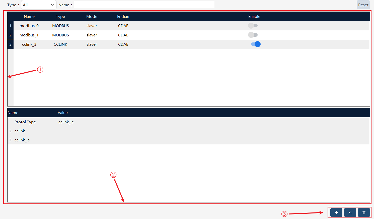
① |
List of bus devices. |
② |
The parameters of the currently selected bus device. |
③ |
The bus device operation buttons, from left to right, are Create, Edit, and Delete. |

Parameter Name |
Parameter Explanation |
Name |
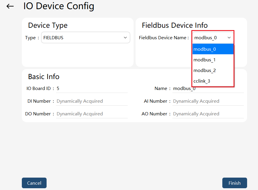
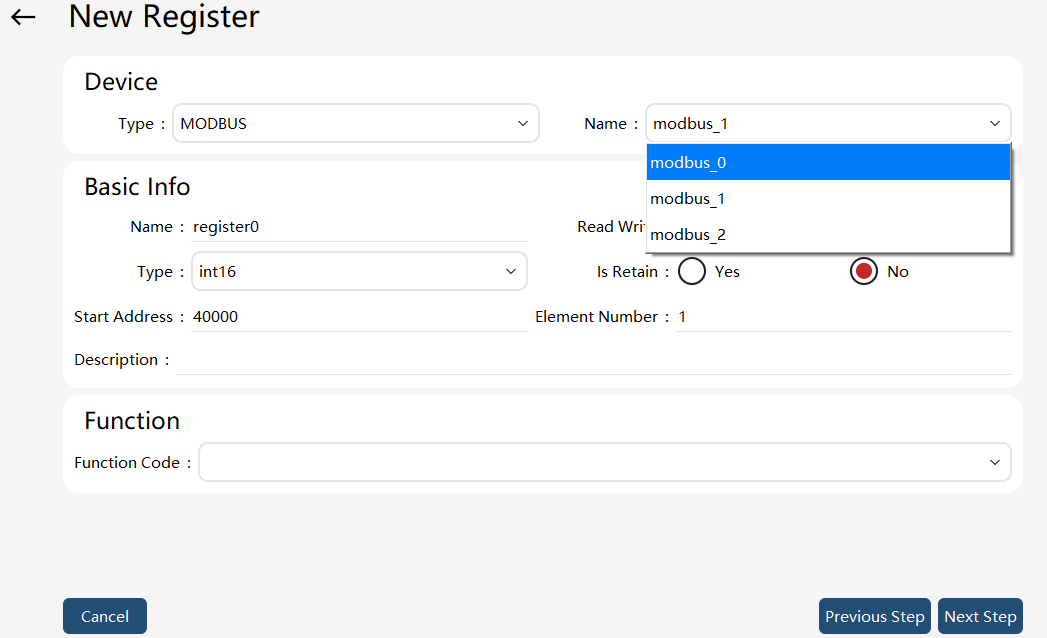
The name is used when configuring "IO Device" and "Register."
As shown in the figure below:
|
Type |
It can be selected when adding/editing a bus device. Only CC-Link, Modbus, EtherCAT, and PROFINET are supported. Note:
|
Type |
It indicates whether the current robot is acting as a master or slave on the bus. |
Endian |
It is mainly for registers. Since each register occupies 2 bytes, there are many hexadecimal sequences of the two bytes. This attribute needs to correspond to the master and the slave, otherwise, the data will not meet the expectations. Four types of endianness are supported: ABCD, CDAB (default), BADC, and DCBA. |
Enabling button |
The bus function can be enabled or disabled through this button. Each bus device to be enabled or disabled individually is supported. |
10.5.2.1 Modbus communication
On the bus device page, click on the bottom right corner  to enter the new communication bus device page, and select the device type as "MODBUS". It supports the TCP and RTU protocol, and the device can be configured as a master or slave.
10.5.2.2 Modbus TCP configuration
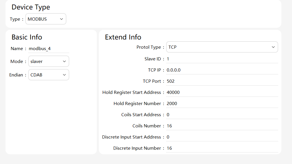
| Parameter | Introduction |
|---|---|
Type |
"master", the robot serves as a master; "slave", the robot acts as a slave; |
Slave ID |
When the robot serves as a slave, ensure that the overall configuration of the bus does not conflict with other slaves. |
TCP/IP |
When the robot serves as a slave, fill in 0.0.0.0, which means all network cards are monitored. |
TCP port |
The port number when the slave uses the TCP protocol. |
Holding register start address |
The start address of the register affected by the function codes 0x03, 0x06, and 0x10. Each register occupies 2 bytes. |
Holding Registers Number |
The number of holding registers from the holding register start address. |
Coil start address |
The start address of the register affected by the function codes 0x01, 0x05, and 0x0F. |
Coils Number |
The number of coil registers from the coil start address. |
Discrete Input Start Address |
The start address of the register affected by the function code 0x02. |
Discrete Input Number |
The number of discrete input registers from the discrete input start address. |
10.5.2.3 Modbus RTU configuration
The Modbus RTU conception is partly the same as the Modbus TCP conception, which will not be repeated here. Only the differences are described as follows:
RTU serial port name: Indicates the serial port medium used for bus communication. Configure it in "Communication" -> "Serial Port Configuration", including the parameters for communication.
10.5.2.4 CC-Link communication
On the bus device page, click on the bottom right corner to enter the new communication bus device page, and select the device type as "CCLINK". It supports the CC-Link and CC-Link IE Field Basic protocol, and the device can be configured as slave only.
10.5.2.5 CC-Link configuration
| Parameter | Introduction |
|---|---|
Protol type |
cclink_ie means the CC-Link IE Field Basic communication protol that directly uses the robot’s Ethernet port. |
cclink_ie NetCard |
Configure which Ethernet card is used for communication. |
cclink_ie Occupied Station Number |
1 to 16 occupied stations can be configured. The default number is 4. Default values are recommended. |
cclink_ie Protol Version |
Ver1 or Ver2 is optional. Please ensure that it is consistent with that of the master. |
10.5.2.6 EtherCAT communication
On the bus device page, click on the bottom right corner to enter the new communication bus device page, and select the device type as "ETHERCAT". EtherCAT can be used to access PROFINET and EtherNet/IP gateway modules.
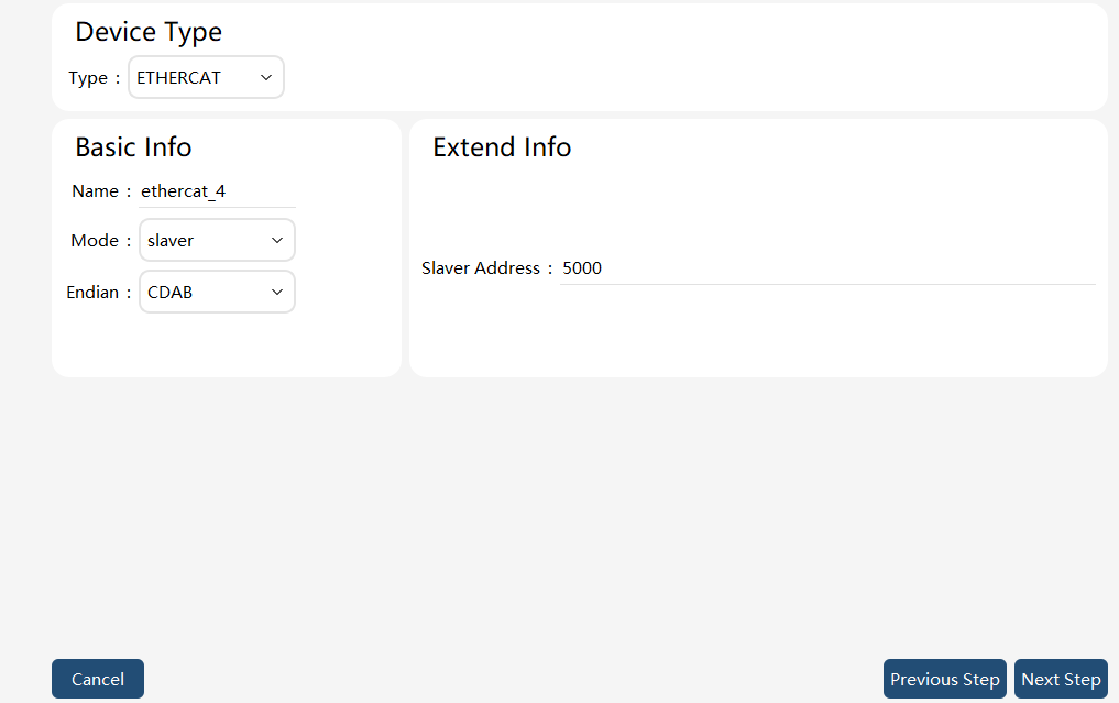
Slaver Address: The slave address number in the EtherCAT bus topology.
Note: Since the EtherCAT slave address number 1000-4000 is occupied by the robot internal devices, to avoid device address conflict, the EtherCAT slave address number of extended devices should not be less than 5000.
10.5.2.7 PROFINET communication
10.5.2.7.1 PROFINET slave
On the bus device page, click on the bottom right corner to enter the new communication bus device page, and select the device type as "PROFINET". The device can be configured as a slave only. One PROFINET slave can be configured for one robot, and multiple robots can join the same PROFINET network by modifying the PROFINET slave name to enable multiple slaves. The model selected for Slots 1-6 should be consistent with the correspondent-side configuration.
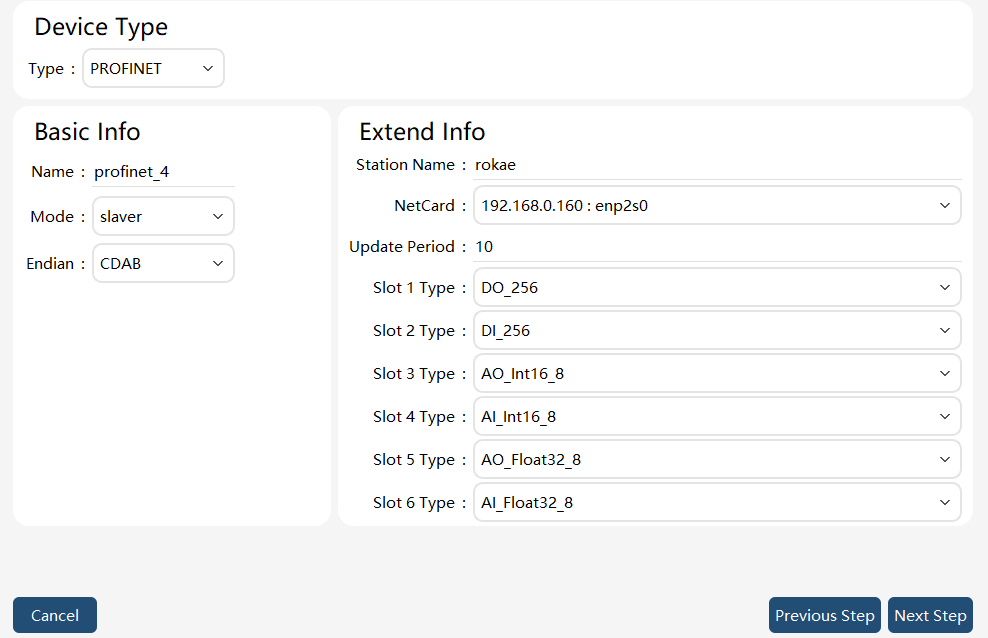
Parameter explanation:
| Parameter | Explanation |
|---|---|
Device type |
Select PROFINET. |
Name |
Equipment code. |
Type |
Only slaver is supported. |
Endian |
Select DCBA generally, depending on the agreement between the communicating parties. |
Station name |
PROFINET slave name. It should be consistent with the correspondent-side configuration. Chinese characters, uppercase letters, and underlines are not allowed. |
NetCard |
Select the network port to connect to the correspondent; includes the network card IP and name. |
Update period |
Default to 10ms, minimum 2ms. |
Slot 1 type |
Only DO_256 model can be selected, indicating that 256 digital quantities are output from the robot to the correspondent via slot 1. |
Slot 2 type |
Only DI_256 model can be selected, indicating that there are 256 digital inputs from the correspondent to the robot via slot 2. |
Slot 3 type |
The option models include AO_Int16_8/ AO_Int16_16/ AO_Int16_32/ AO_Int16_64/ AO_Int16_128/ AO_Int16_256. |
Slot 4 type |
The option models include AI_Int16_8/ AI_Int16_16/ AI_Int16_32/ AI_Int16_64/ AI_Int16_128/ AI_Int16_256. |
Slot 5 type |
The option models include AO_Float32_8/ AO_Float32_16/ AO_Float32_32/ AO_Float32_64/ AO_Float32_128/ AO_Float32_256. |
Slot 6 type |
The option models include AI_Float32_8/ AI_Float32_16/ AI_Float32_32/ AI_Float32_64/ AI_Float32_128/ AI_Float32_256. |
10.5.2.7.2 PROFINET master
On the bus device page, click on the bottom right corner to enter the new communication bus device page, select the device type as "PROFINET", and select the mode as "master". A robot supports setting up a PROFINET master.
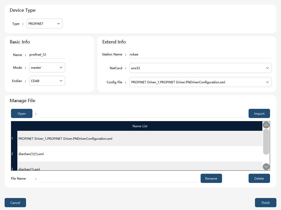
Parameter explanation:
| Parameter | Explanation |
|---|---|
Device type |
Select PROFINET. |
Name |
Equipment code. |
Type |
master |
Endian |
The master only supports CDAB. |
Station name |
PROFINET master name |
NetCard |
Select the network port to connect with the communication partner. |
Configuration files |
Select the configuration file for connecting with the communication partner. |
Manage configuration files |
Import and edit configuration files. |
On |
Open the system directory to select the files to import. |
Import |
Import configuration files. |
File list |
Display existing configuration files. |
File name |
Name of the currently selected file. |
Rename |
Rename the selected file |
Delete |
Delete the currently selected file |
10.5.2.8 Ethernet/IP communication
On the bus device page, click on the bottom right corner to enter the new communication bus device page, and select the device type as "EtherNetIP". The device can be configured as a slave only. A single robot supports the configuration of one EtherNet/IP slave station.
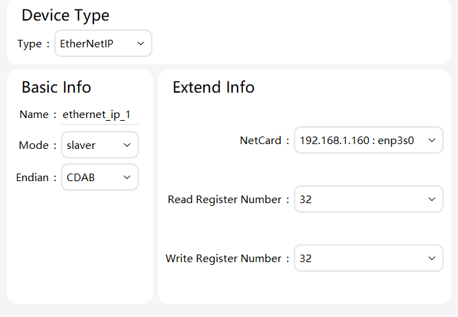
Parameter explanation:
| Parameter | Explanation |
|---|---|
Device type |
That is, EtherNetIP. |
Name |
Bus device name, cannot be the same as the names of other bus devices. |
Type |
Only slaver is supported. |
Endian |
Select CDAB generally, depending on the agreement between the communicating parties. |
NetCard |
Select the name of the network card connecting to the EtherNet/IP master station. The dropdown box will display the IP address and name of the network card. |
Read-only Registers Number |
Number of read-only registers for the EtherNet/IP slave station: Each register represents 2 bytes. Options are 32, 64, 128, and 248 registers. |
Write-only Registers Number |
Number of write-only registers for the EtherNet/IP slave station: Each register represents 2 bytes. Options are 32, 64, 128, and 248 registers. |
Notes:
-
Only one EtherNet/IP bus device is supported. Attempting to create more will result in an error message.
-
Register addresses start from 0. If 32 is selected, it indicates that the device has registers with addresses from 0 to 31. When configuring register mappings in the "Registers" interface, pay attention to the address range.
-
Read-only and write-only are defined from the perspective of the xCore control system: Read-only registers correspond to EtherNet/IP master Output data; write-only registers correspond to EtherNet/IP master Input data.
-
The number of read-only and write-only registers also represents the amount of communication data. The more data, the greater the communication load. Therefore, it is recommended to select the smallest number of registers that meets the requirements.
-
The number of bytes for Input and Output data configured in the master station should match the number of bytes contained in the write-only and read-only registers of the slave station, respectively. Otherwise, communication may fail.
-
The read-only and write-only registers of the EtherNet/IP bus device are two separate data areas. The addresses for configured read-only and write-only registers can overlap.
-
The EtherNet/IP slave station of the xCore control system does not provide an EDS file by default. Its Input Assembly Instance ID is 1, and its Output Assembly Instance ID is 2. The master station must match these settings during configuration; otherwise, communication may fail.