2.1 Introduction
This chapter describes the safety principles and procedures that need to be noted when using the robot.
The contents related to the design and installation of the external safety protection devices of the robot are not covered in this chapter. You can contact your system integrator to obtain such information.
2.2 Safety responsibilities
ROKAE is dedicated to but not liable for providing reliable safety information. Even if all operations are carried out according to the safe operation instructions, we can not guarantee that our industrial robots will not cause personal and property losses.
2.3 Safety symbols
There may be different degrees of danger when operating the robot in accordance with the Manual, so there will be a special safety symbol in the vicinity of dangerous operation instructions to remind the user to be careful. The contents include:
An icon that indicates safety level and the corresponding name, such as warning, danger, note, etc.;
A brief description given to illustrate the possible consequences if the operator fails to eliminate the danger;
The operating instructions on how to eliminate dangers.
2.3.1 Safety level
| Icon | Name | Explanation |
|---|---|---|
|
DANGER |
Failure to follow the contents with this sign will cause serious or even fatal harm to the personnel, and also will/may cause serious damage to the robot. |
|
Warning |
Failure to follow the contents with this sign may cause serious and even fatal personal injury, and also will cause great damage to the robot. |
|
Electric shock hazard |
It indicates that the current operation may cause an electric shock hazard, which will result in a serious or even fatal injury. |
|
Caution |
Failure to follow the contents with this sign may cause personal injury, and also may cause damage to the robot. |
|
ESD |
It indicates that the components involved in the current operation are sensitive to static electricity. Failure to follow the contents with this sign may cause damage to the components. |
|
Note |
It is used to prompt some important information or prerequisites. |


2.3.2 Hazard description
| Icon | Name | Explanation |
|---|---|---|
|
Squeezing |
Operators and maintenance personnel who enter the motion range of the robot during debugging, repair, overhaul, and tool clamping may be injured. |
|
Hand pinching |
The maintenance personnel have a risk of hand pinching when approaching belt drive parts during the maintenance. |
|
Strike |
Operators and maintenance personnel who enter the motion range of the robot during debugging, repair, overhaul, and tool clamping may be seriously injured. |
|
Friction |
Operators and maintenance personnel who enter the motion range of the robot during debugging, repair, overhaul, and tool clamping may be injured. |
|
Parts flying out |
Operators and maintenance personnel who enter the motion range of the robot during debugging, repair, overhaul, and tool clamping may be seriously injured if tools or work objects are ejected due to loose clamping. |
|
Fire |
Electrical short-circuit and burning wires/devices may cause fire, which may result in serious injuries. |
|
Hot surface |
During the maintenance and repair of the equipment, if maintenance personnel touch the robot’s hot surface, they may be burned. |


2.4 Safe stop
There are three ways to stop the robot: STOP 0, STOP 1, and STOP 2.
Safe stop refers to a stop triggered by the safety controller, which only supports STOP 0 and STOP 1, while STOP 2 can only be triggered by the control system.
| Stop mode | Description |
|---|---|
STOP 0 |
As the stop method of the highest safety level, STOP 0 cuts off the power supply of motors and closes the band-type brakes of all joints immediately after it is triggered. During the stopping process, the robot is uncontrolled, so it may deviate from the programmed path after it is stopped. |
STOP 1 |
Once STOP 1 is triggered, the control system immediately executes the deceleration process along the programmed path. Thereafter, whether the robot comes to a complete stop or not, the safety controller will cut off the power supply of motors and close the band-type brakes of all joints. Since the stop is controlled, in most cases, the robot will finally stop on the programmed path. Therefore, This emergency stop method provides the best protection for nearby equipment. |
STOP 2 |
Once STOP 2 is triggered, the control system immediately executes the deceleration along the programmed path until the robot stops completely. The power supply of the motors remains on and the band-type brakes are still open, while the robot stays in the current position. |
|
Emergency stop is only used to stop the robot immediately in dangerous circumstances. Emergency stop shall not be used for normal stops. Otherwise, extra and unnecessary wear may be caused to the brake and transmission system, which will eventually reduce the robot’s service life. |
2.5 Safety devices
2.5.1 Emergency stop (E-stop)
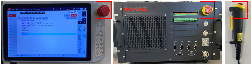
Emergency stop buttons are for manually triggering an emergency stop, and most of them are red in the shape of a mushroom head. In general, a yellow substrate, protective casing, or warning sign is also attached to the emergency stop button.
The emergency stop button is mechanically locked through the safety lock mechanism when it is pressed and must be reset through manual release. Most emergency stop buttons are released by rotation along the rotation direction indicated on the button surface. Additionally, some buttons also support releasing by upward pulling.
2.5.2 Enabling device
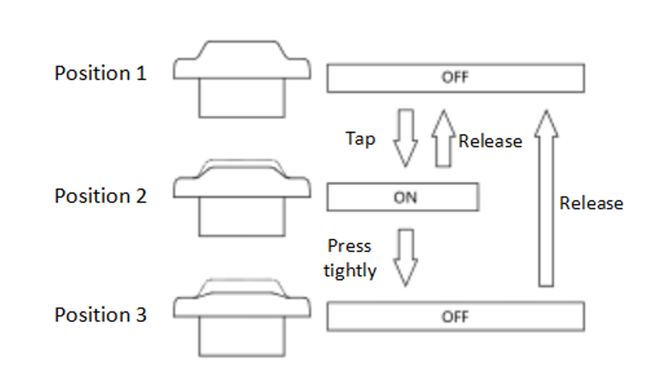
The enabling device is a special switch with 2 segments of pressing and 3 positions, which is also called three-position enabling switch (hereinafter referred to as “enabling switch”), and is used to control the on and off of the power supply of the robot in the manual mode, thus realizing the motion enabling of the robot. The motor power is powered on only when the enabling switch is pressed and kept in the middle so that the robot is in a state ready for motion. Releasing or pressing the switch all the way down will cut off the motor power.
|
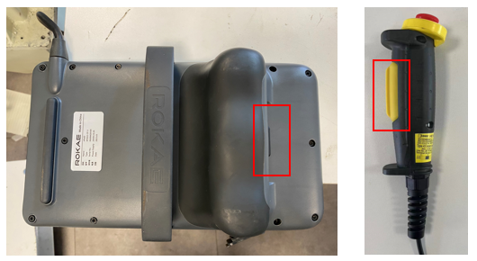
The yellow button on the Handheld Enabling Device is an enabling switch. When the enabling switch is pressed and held in the middle position, the power supply of the motor is turned on and automatically enabled, and the system is in a power-on state, and you can jog the robot or execute a program. Releasing or pressing the switch all the way down will cut off the motor power and make the system return to the power-off state. In order to use the Teach Pendant safely, the following requirements must be observed:
|
|
It is strictly prohibited to use external devices to keep the enabling switch locked or stopped in the middle position! |
2.6 Safety precautions in various situations
2.6.1 Safety precautions in manual mode
In manual mode, the motion of the robot is under manual control. You can only Jog the robot or execute a program when the enabling switch is held in the middle position. The manual mode is used during the programming and debugging of the robot, as well as the commissioning of the workstation.
2.6.1.1 Speed limit in manual mode
The motion velocity of the robot end-effector is limited to less than 250 mm/s in manual mode, that is, no matter when you Jog the robot or execute a program, regardless of the set velocity in the program, the maximum motion velocity of the robot end-effector will not exceed 250 mm/s.
2.6.1.2 Bypassing external safety signals
In manual mode, signals of external safety devices such as the safety door and safety grating will be bypassed, i.e. in manual mode, the system can still perform motor-enabling operations even if the safety door is opened, and the system will not prompt the safety door opening information for the convenience of debugging.
2.6.2 Safety precautions in auto mode
The auto mode is used for robot program running during the formal production process. In auto mode, the enabling switch will be bypassed so that the robot can run automatically without manual intervention.
2.6.3 Safety requirements for installation and operation
-
Handling and installation of the robot equipment must be carried out according to the methods described in the Manual. Otherwise, the robot may fall due to misoperation, thus leading to personal injury and death or equipment damage.
-
When the robot equipment is put into use for the first time after installation, it is necessary to run it at low velocity first and then gradually increase the velocity rather than running it at high velocity from the start.
-
By default, program and system variable information is stored in the controller storage device. In order to prevent data loss caused by accidents, it is recommended that the user makes data backups regularly.
2.6.4 Safety requirements for debugging
Debugging shall be carried out outside the safeguarded space as much as possible. When debugging must be carried out inside the safeguarded space, special attention shall be paid to the following matters:
-
Carefully check the situation inside the safeguarded space and enter into it only after confirming there is no danger.
-
Confirm the positions of all debugging personnel inside the safeguarded space.
-
Confirm the status of the entire system before proceeding with the work.
-
Make sure that the emergency stop button can be pressed whenever necessary.
-
Run the robot at low velocity.
-
When the above debugging is finished, the debugging personnel must stay outside the safeguarded space.
2.6.5 Safety requirements for maintenance
-
It is necessary to carefully check the situation in the safeguarded space and confirm that there is no danger before entering the safeguarded space. The positions of all maintenance personnel in the safeguarded space shall be confirmed.
-
When the power supply is switched on, some maintenance operations may pose a risk of electric shock. Therefore, the power supply of the robot equipment and system needs to be cut off before the maintenance is carried out.
-
During the maintenance, other personnel shall be prevented from switching on the power supply accidentally.
-
To avoid unnecessary personal injury or adverse impact on the equipment, you shall not place any part of your body on any part of the robot equipment during the operation.
-
Appropriate lighting shall be provided during the maintenance.
-
In case of part replacement, make sure to use parts specified by ROKAE. Otherwise, the robot equipment may be damaged.
-
Parts removed during the replacement (such as screws) shall be correctly installed back to their original positions. If you find the parts not enough or redundant, you need to confirm again and make sure to install them correctly.
2.6.6 Safe handling on the production line
In most cases, the robot is just a part of the production line. Therefore, robot faults will not only affect the robot itself, but may also affect the entire production line. Likewise, problems with other parts of the production line may also affect the robot. For this reason, a fault remedial plan shall be designed by personnel who are very familiar with the entire production line to improve the safety of the whole system.
-
Pay attention to other devices that interact with the robot
For example, when a robot needs maintenance, you must first remove it from the production line, as well as remove other devices interacting with the robot, such as the robot responsible for feeding materials to the above robot.
-
Pay attention to other running devices around the robot
For example, robots on the production line need to grab work objects from the conveyor belt. Therefore, when a robot fails, in order to guarantee uninterrupted production, the conveyor belt may keep running while the robot is being repaired. The robot maintenance personnel must pay extra attention to safety, give advance consideration to the risks that might arise from the running conveyor belt, and develop detailed safety measures for working in such an environment.
2.6.7 Safe handling of fire
It is required to keep calm when a fire hazard is imminent or has not yet begun to spread. You can use on-site fire-extinguishing devices to put out the flame. It is strictly prohibited to use water to put out a fire caused by a short-circuit fault.
|
The fire-extinguishing devices in the working space of the robot shall be self-prepared by the user, and the user shall choose appropriate fire-extinguishing devices according to the actual situation. |
If the fire has spread and is beyond control, the workers on the site shall notify other workers immediately to give up their personal belongings and evacuate immediately through emergency exits rather than try to put out the fire. DO NOT use the elevators, and be sure to inform the fire brigade during evacuation. If one person’s clothing catches fire, ask him/her not to run but to lie flat on the ground immediately, and put out the fire using clothes or other suitable items and methods.
2.6.8 Safe handling of electric shock
When someone gets an electric shock, do not panic and cut off the power supply immediately.
Appropriate methods and measures shall be adopted without hesitation according to specific site conditions. Generally, there are several methods and measures as follows:
-
If the power switch or button is very near to the point of the electric shock, it shall be switched off at once to cut off the power supply.
-
If the power switch or button is far away from the point of the electric shock, it is recommended to use insulated pliers or an axe, knife, and shovel with a dry wooden handle to cut off the live wire on the mains side (power supply side), and the cut wire must not contact with the human body.
-
If the wire is over or under the body of the victim, it is suggested to use a dry stick, board, bamboo pole, or other tools with an insulated handle (by gripping the insulated handle) to remove the wire. No metal bar or wet object shall be used to prevent the rescuer from also getting an electric shock.
Handling of the victim after separation from the power source
-
If the victim is conscious, make him/her lie on the back, keep a close watch over him/her, and let him/her not stand or walk for the time being.
-
If the victim is confused, make him/her lie on the back to keep the airways open, and call the victim or pat him/her on the shoulder at an interval of 5 seconds to judge if he/she loses consciousness completely. Do not call the victim by shaking his/her head. Meanwhile, contact the hospital as soon as possible.
-
If the victim loses consciousness, confirm his/her respiratory conditions and heartbeat within 10 seconds. If neither breath nor arterial pulse is sensed, the victim may have a cardiac arrest and shall be given immediate first aid treatment by cardiopulmonary resuscitation.